43
107006-11 EN FR26 GLO 0300 Printed in Germany
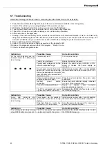
6.7 Troubleshooting
Obtain the following information before contacting the After Sales Service for assistance:
1. Serial Number and Manufacturing Date Code of the device (information available on the rating plate).
2. Version of the software you are using (displayed in the welcome window)
3. What is the Operating System from which you are running the PC Software?
4. Type of power cable in use (with an external filter or not, provide listing if possible).
5. Type of RS 232 cable in use (with a shielding or not, provide listing if possible).
6. Short description of the application.
7. Drawing of the Alarm and Safety Zones, as well as the environment with measured distances. This can be obtained by
using the FFSE.EXE program and the “Monitor” menu for a few seconds, then save the parameter file when exiting. This
will create a PRM file with your protection zones and an OWS file containing the profiles measured with monitor.
8. Did you define an external test target?
9. Status of the LED indicators and flashing sequence of the diagnostic LED.
10. Status of the diagnostic window in the FF-SE program , “ Monitor ” menu
11. Refer to troubleshooting table below.
Indication
Possible Cause
Corrective Action
All the LED indicators are not
illuminated and the rotating head
is not turning.
Power supply is off
Turn on power supply
Fuse(s) may be blown.
Replace fuse(s) as required.
Power supply voltage may not be
within the specified range.
Ensure the power supply is 24Vdc +/-15%.
Adjust or replace the power supply as
required.
Power supply may not be able to
absorb the current inrush during
startup (especially when several
laser scanners are powered from
the same source).
Install a power supply with a current capability
that can absorb the current inrush (2A for 100
ms)
Cable connection between power
supply and sensor is open.
Properly seat and tighten the sensor cable
connection.
Incorrect power source
connection
Ensure the power cable is properly connected
to + and - of the power source.
Connector
is
damaged/broken
Repair or replace cable connector
pins/receptacles as required.
The PC is connected and sends
a permanent reset to the sensor
Disconnect the RS232 interface cable or start
the FFSE.EXE program
Indication
Possible Cause
Corrective Action
Some LED indicators are
illuminated but the rotating head
is not turning.
Power supply may be unable to
absorb the current inrush during
startup.
Install a power supply with a current capability
that can absorb the current inrush oneword.
Drive belt broken or motor has
malfunction or is in operable.
Send the sensor to Honeywell for repair (see
section 8.2 Sales and Service).
Indication
Possible Cause
Corrective Action
The rotating head stops turning
when RS232 cable is connected
The PC is connected and sends
a permanent reset to the sensor
Disconnect the RS232 interface cable or start
the FFSE.EXE program.
Summary of Contents for SYA14 Series
Page 2: ...2 107031 23 EN FR26 GLO 1199 Printed in France This page has been left intentionally blank ...
Page 6: ...6 107031 23 EN FR26 GLO 1199 Printed in France This page has been left intentionally blank ...
Page 26: ...26 107031 23 EN FR26 GLO 1199 Printed in France This page has been left intentionally blank ...
Page 62: ...62 107031 23 EN FR26 GLO 1199 Printed in France This page has been left intentionally blank ...
Page 70: ...70 107031 23 EN FR26 GLO 1199 Printed in France This page has been left intentionally blank ...
Page 76: ...76 107031 23 EN FR26 GLO 1199 Printed in France This page has been left intentionally blank ...
Page 78: ...78 107031 23 EN FR26 GLO 1199 Printed in France This page has been left intentionally blank ...
Page 79: ...107031 23 EN FR26 GLO 1199 Printed in France 79 8 CE Declaration of Conformity ...
Page 80: ...80 107031 23 EN FR26 GLO 1199 Printed in France This page has been left intentionally blank ...
Page 84: ......
Page 158: ......
Page 160: ......
Page 161: ...For application help call 1 800 537 6945 Honeywell MICRO SWITCH Sensing and Control 80 ...
Page 165: ...3 107022 14 EN FR26 GLO 0100 Printed in Germany This page has been left intentionally blank ...
Page 201: ...39 107022 14 EN FR26 GLO 0100 Printed in Germany This page has been left intentionally blank ...
Page 205: ...43 107022 14 EN FR26 GLO 0100 Printed in Germany This page has been left intentionally blank ...
Page 207: ...45 107022 14 EN FR26 GLO 0100 Printed in Germany This page has been left intentionally blank ...
Page 208: ...107022 14 EN FR26 GLO 0100 Printed in Germany 46 9 Declaration of Conformity ...
Page 219: ...11 107006 11 EN FR26 GLO 0300 Printed in Germany This page has been left intentionally blank ...
Page 229: ...21 107006 11 EN FR26 GLO 0300 Printed in Germany This page has been left intentionally blank ...
Page 257: ...49 107006 11 EN FR26 GLO 0300 Printed in Germany This page has been left intentionally blank ...
Page 260: ...107006 11 EN FR26 GLO 0300 Printed in Germany 52 9 3 Declaration of conformity ...
Page 340: ...Safety Perimeter Guarding Installation Manual FF SPS4 Series Safety Perimeter Guarding ...
Page 536: ...2 107004 15 EN FR26 ROW 0899 Printed in France This page has been left intentionally blank ...
Page 538: ...4 107004 15 EN FR26 ROW 0899 Printed in France This page has been left intentionally blank ...
Page 542: ...107004 15 EN FR26 ROW 0899 Printed in France 8 This page has been left intentionally blank ...
Page 620: ...86 107004 15 EN FR26 ROW 0899 Printed in France This page has been left intentionally blank ...
Page 624: ...90 107004 15 EN FR26 ROW 0899 Printed in France This page has been left intentionally blank ...
Page 626: ...92 107004 15 EN FR26 ROW 0899 Printed in France This page has been left intentionally blank ...
Page 627: ...107004 15 EN FR26 ROW 0899 Printed in France 93 8 CE Declaration of Conformity ...
Page 628: ...94 107004 15 EN FR26 ROW 0899 Printed in France This page has been left intentionally blank ...


