Description and Operation
FF-SPS4 Series Installation Manual
8 Honeywell
•
MICRO SWITCH Sensing and Control
For application help: call 1-800-537-6945
Receiver Indicators
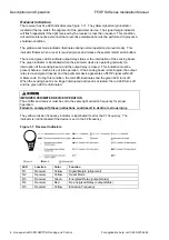
The receiver has five LED indicators (see figure 1-7). The yellow signal margin indicator
located at the top aids in the alignment of the perimeter device. The signal margin indicator
will flash repeatedly if the light received by the receiver is less than required. This condition
will alert maintenance personnel that preventive maintenance must be performed to prevent a
shutdown condition.
The yellow reset mode indicator illuminates during normal operation (manual mode). This
indicator flickers when a reset is required (press and release the system restart push-button).
The red and green LEDs indicate output relay status or the interruption of the sensing beam.
The green indicator is illuminated when the perimeter device is operating normally (no
interruption of the sensing beam) and the output relay is closed. This indication must be
present before a machine is put into operation. If the sensing beam is interrupted, the output
relay is de-energized (opens) and the perimeter device generates a STOP signal within 20
milliseconds. During this condition, the red LED illuminates and the green LED turns off.
When the sensing beam is no longer interrupted and reset is actuated, the red LED turns off
and the green LED is illuminated.
IMPROPER PERIMETER DEVICE OPERATION
The emitter and receiver must be set to the same light emission frequency for proper
operation.
Failure to comply with these instructions could result in death or serious injury.
The yellow emission frequency indicator is illuminated if set for the F1 frequency. The
indicator is not illuminated if the device is set to the F2 frequency.
Figure 1-7 Receiver Indicators
LED
Location
Color
Function
R1
Receiver
Yellow
Signal Margin (alignment)
R2
Receiver
Yellow
Reset Mode
R3
Receiver
Green
Energized Relay (output status)
R4
Receiver
Red
De-energized Relay (output status)
R5
Receiver
Yellow
Emission Frequency
Summary of Contents for SYA14 Series
Page 2: ...2 107031 23 EN FR26 GLO 1199 Printed in France This page has been left intentionally blank ...
Page 6: ...6 107031 23 EN FR26 GLO 1199 Printed in France This page has been left intentionally blank ...
Page 26: ...26 107031 23 EN FR26 GLO 1199 Printed in France This page has been left intentionally blank ...
Page 62: ...62 107031 23 EN FR26 GLO 1199 Printed in France This page has been left intentionally blank ...
Page 70: ...70 107031 23 EN FR26 GLO 1199 Printed in France This page has been left intentionally blank ...
Page 76: ...76 107031 23 EN FR26 GLO 1199 Printed in France This page has been left intentionally blank ...
Page 78: ...78 107031 23 EN FR26 GLO 1199 Printed in France This page has been left intentionally blank ...
Page 79: ...107031 23 EN FR26 GLO 1199 Printed in France 79 8 CE Declaration of Conformity ...
Page 80: ...80 107031 23 EN FR26 GLO 1199 Printed in France This page has been left intentionally blank ...
Page 84: ......
Page 158: ......
Page 160: ......
Page 161: ...For application help call 1 800 537 6945 Honeywell MICRO SWITCH Sensing and Control 80 ...
Page 165: ...3 107022 14 EN FR26 GLO 0100 Printed in Germany This page has been left intentionally blank ...
Page 201: ...39 107022 14 EN FR26 GLO 0100 Printed in Germany This page has been left intentionally blank ...
Page 205: ...43 107022 14 EN FR26 GLO 0100 Printed in Germany This page has been left intentionally blank ...
Page 207: ...45 107022 14 EN FR26 GLO 0100 Printed in Germany This page has been left intentionally blank ...
Page 208: ...107022 14 EN FR26 GLO 0100 Printed in Germany 46 9 Declaration of Conformity ...
Page 219: ...11 107006 11 EN FR26 GLO 0300 Printed in Germany This page has been left intentionally blank ...
Page 229: ...21 107006 11 EN FR26 GLO 0300 Printed in Germany This page has been left intentionally blank ...
Page 257: ...49 107006 11 EN FR26 GLO 0300 Printed in Germany This page has been left intentionally blank ...
Page 260: ...107006 11 EN FR26 GLO 0300 Printed in Germany 52 9 3 Declaration of conformity ...
Page 340: ...Safety Perimeter Guarding Installation Manual FF SPS4 Series Safety Perimeter Guarding ...
Page 536: ...2 107004 15 EN FR26 ROW 0899 Printed in France This page has been left intentionally blank ...
Page 538: ...4 107004 15 EN FR26 ROW 0899 Printed in France This page has been left intentionally blank ...
Page 542: ...107004 15 EN FR26 ROW 0899 Printed in France 8 This page has been left intentionally blank ...
Page 620: ...86 107004 15 EN FR26 ROW 0899 Printed in France This page has been left intentionally blank ...
Page 624: ...90 107004 15 EN FR26 ROW 0899 Printed in France This page has been left intentionally blank ...
Page 626: ...92 107004 15 EN FR26 ROW 0899 Printed in France This page has been left intentionally blank ...
Page 627: ...107004 15 EN FR26 ROW 0899 Printed in France 93 8 CE Declaration of Conformity ...
Page 628: ...94 107004 15 EN FR26 ROW 0899 Printed in France This page has been left intentionally blank ...


