107016-11 EN FR26 GLO 1199 Printed in Germany
3
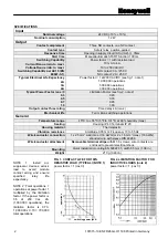
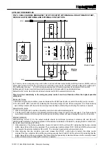
FIG 3. CURRENT VS. TEMPERATURE LIMIT
Figure 3. displays the maximal recommended external
temperature versus the total load of all the safety module
contacts. To use this curve, do the following:
(1)
Follow the horizontal line from the value (vertical axis)
equal to the current inside the safety module contacts
and note intersection of the appropriate curve.
(2)
Follow the intersection point down to determine the
maximal recommended ambient temperature. (Ex: 4
A current inside each two safety contacts, then T = 43
°
C (109
°
F).
If the module is located in a higher temperature
environment, the lifetime of the electronic components
may be reduced. Ventilation of the cabinet may be
required.
MECHANICAL INSTALLATION
The FF-SRS5934 must be installed inside a NEMA 3 (IEC
IP54) rating enclosure or better. The module can be
clipped easily onto a 45mm width DIN rail (see figures 4
and 5 below for installation and removal).
FIG 4. MOUNTING DIMENSIONS (for reference
only)
FIG 5. INSTALLATION DIAGRAM
CONTROL RELIABILITY
“Control Reliability” means that “the device, system or
interface shall be designed, constructed and installed
such that a single component failure within the device,
interface or system shall not prevent normal stopping
action from taking place but shall prevent a successive
machine cycle.” (ANSI B11.19-1990, 5.5)
OSHA 29 CFR 1910.217 states that “the control system
shall be constructed so that a failure within the system
does not prevent the normal stopping action from being
applied to the press when required, but does prevent
initiation of a successive stroke until the failure is
corrected. The failure shall be detectable by a simple test,
or indicated by the control system.”
Honeywell uses self-checking techniques which combine
reliability with safety. This means that a faulty component
in our system will make the safety control modules fail in a
safe mode.
The FF-SRS5934 safety control module functions with
dual internal channel redundancy and positive self-check
monitoring, but relies on a single safety input. If a single
safety input does not provide the level of safety required,
use one of tne dual channel safety control modules (FF-
SRS5925, FF-SRS5935, FF-SRS5988).
The design of this device meets the highest requirements
(Category 4 as described in the EN 954 European norm).
Category 4 safety control modules are designed and
manufactured in such a way that a single breakdown or
an accumulation of internal failures does not lead to the
loss of the safety function when a dangerous situation
arises. The safety function is maintained on a
permanent basis.
a Width: 45 mm 1.77 in.
b Height: 74 mm 2.91 in.
c Depth: 121 mm 4.76 in.
Rail
Current via two contact rows
(same current for each contact row)
Current via one contact row
C
onti
nuous current
Ambient Temperature
Summary of Contents for SYA14 Series
Page 2: ...2 107031 23 EN FR26 GLO 1199 Printed in France This page has been left intentionally blank ...
Page 6: ...6 107031 23 EN FR26 GLO 1199 Printed in France This page has been left intentionally blank ...
Page 26: ...26 107031 23 EN FR26 GLO 1199 Printed in France This page has been left intentionally blank ...
Page 62: ...62 107031 23 EN FR26 GLO 1199 Printed in France This page has been left intentionally blank ...
Page 70: ...70 107031 23 EN FR26 GLO 1199 Printed in France This page has been left intentionally blank ...
Page 76: ...76 107031 23 EN FR26 GLO 1199 Printed in France This page has been left intentionally blank ...
Page 78: ...78 107031 23 EN FR26 GLO 1199 Printed in France This page has been left intentionally blank ...
Page 79: ...107031 23 EN FR26 GLO 1199 Printed in France 79 8 CE Declaration of Conformity ...
Page 80: ...80 107031 23 EN FR26 GLO 1199 Printed in France This page has been left intentionally blank ...
Page 84: ......
Page 158: ......
Page 160: ......
Page 161: ...For application help call 1 800 537 6945 Honeywell MICRO SWITCH Sensing and Control 80 ...
Page 165: ...3 107022 14 EN FR26 GLO 0100 Printed in Germany This page has been left intentionally blank ...
Page 201: ...39 107022 14 EN FR26 GLO 0100 Printed in Germany This page has been left intentionally blank ...
Page 205: ...43 107022 14 EN FR26 GLO 0100 Printed in Germany This page has been left intentionally blank ...
Page 207: ...45 107022 14 EN FR26 GLO 0100 Printed in Germany This page has been left intentionally blank ...
Page 208: ...107022 14 EN FR26 GLO 0100 Printed in Germany 46 9 Declaration of Conformity ...
Page 219: ...11 107006 11 EN FR26 GLO 0300 Printed in Germany This page has been left intentionally blank ...
Page 229: ...21 107006 11 EN FR26 GLO 0300 Printed in Germany This page has been left intentionally blank ...
Page 257: ...49 107006 11 EN FR26 GLO 0300 Printed in Germany This page has been left intentionally blank ...
Page 260: ...107006 11 EN FR26 GLO 0300 Printed in Germany 52 9 3 Declaration of conformity ...
Page 340: ...Safety Perimeter Guarding Installation Manual FF SPS4 Series Safety Perimeter Guarding ...
Page 536: ...2 107004 15 EN FR26 ROW 0899 Printed in France This page has been left intentionally blank ...
Page 538: ...4 107004 15 EN FR26 ROW 0899 Printed in France This page has been left intentionally blank ...
Page 542: ...107004 15 EN FR26 ROW 0899 Printed in France 8 This page has been left intentionally blank ...
Page 620: ...86 107004 15 EN FR26 ROW 0899 Printed in France This page has been left intentionally blank ...
Page 624: ...90 107004 15 EN FR26 ROW 0899 Printed in France This page has been left intentionally blank ...
Page 626: ...92 107004 15 EN FR26 ROW 0899 Printed in France This page has been left intentionally blank ...
Page 627: ...107004 15 EN FR26 ROW 0899 Printed in France 93 8 CE Declaration of Conformity ...
Page 628: ...94 107004 15 EN FR26 ROW 0899 Printed in France This page has been left intentionally blank ...


