Installation Instructions for the
ISSUE 3
MICRO SWITCH Maintained Cable Pull Safety Limit
Switch With Snap Action Head
PK 81592
MICRO SWITCH Sensing and Control
IMPROPER INSTALLATION
•
Consult all local, state, and national law, rules,
codes, and regulations relating to the use of
safety switches, machine interfaces and safety
monitoring that affect safety.
•
Strictly adhere to all installation instructions.
Failure to comply with these instructions
could result in death or serious injury.
IMPROPER INSTALLATION
•
Do not use input/output (I/O) function (look to see
if SDS or Smart Distributed System is on
nameplate) in emergency-stop applications.
Ensure I/O is used for monitoring only.
Failure to comply with these instructions
could result in death or serious injury.
GENERAL INFORMATION
•
The Maintained Cable Pull Safety Limit Switch is
designed for use in emergency stop applications.
•
Single or duplex head Cable Pull Safety Limit
Switches are designed to forcibly disconnect a set
of direct acting switch contacts.
•
Direct acting switch contacts are held closed
when actuating cables are under proper tension.
When cable is pulled, slackened or broken, a cam
positively opens the switch contacts.
•
Snap action operating head causes switch
contacts to change state and mechanically latch
virtually simultaneously when the cable is pulled
to the actuating position.
•
Switch contacts remain open until switch is reset
by manually depressing the reset button located
on the actuated operating head.
•
When direct acting switch contacts open, auxiliary
contacts also actuate: open contacts close and
closed contacts open.
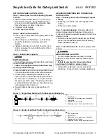
SINGLE HEAD VERSION (Figure 1)
•
Direct acting switch contact: 1 NC (normally
closed).
•
Auxiliary contact: 1 NO (normally open).
•
Head may be positioned in any of four directions.
Figure 1: Single Head Version
DUPLEX HEAD VERSION (Figure 2)
•
Primary basic switch (left side of switch):
−
Direct acting switch contact: 1 NC.
−
Auxiliary contact: 1 NO.
•
Auxiliary basic switch (right side of switch):
−
Four options available.
•
Heads may be positioned in any of three
directions, allowing actuating cables to run in
opposite directions or at right angles to one
another.
Figure 2: Duplex Head Version
AUXILIARY CONTACTS
•
Additional contacts are electrically isolated from
the direct acting switch contacts. These are used
for monitoring or signaling, i.e., indicators, pilot
lights and alarms.
MAXIMUM CABLE LENGTH
•
Depending upon variations in ambient
temperature, maximum length in a single direction
is 200 ft (60 m), for a total of 400 ft (120 m).
TENSION INDICATOR
•
Convenient tension indicator line on switch
plunger indicates proper preset cable tension.
OTHER FEATURES AVAILABLE
•
Conduit openings and indicator/pilot light options.
•
Hardware kits and cables for various length
installations.
Summary of Contents for SYA14 Series
Page 2: ...2 107031 23 EN FR26 GLO 1199 Printed in France This page has been left intentionally blank ...
Page 6: ...6 107031 23 EN FR26 GLO 1199 Printed in France This page has been left intentionally blank ...
Page 26: ...26 107031 23 EN FR26 GLO 1199 Printed in France This page has been left intentionally blank ...
Page 62: ...62 107031 23 EN FR26 GLO 1199 Printed in France This page has been left intentionally blank ...
Page 70: ...70 107031 23 EN FR26 GLO 1199 Printed in France This page has been left intentionally blank ...
Page 76: ...76 107031 23 EN FR26 GLO 1199 Printed in France This page has been left intentionally blank ...
Page 78: ...78 107031 23 EN FR26 GLO 1199 Printed in France This page has been left intentionally blank ...
Page 79: ...107031 23 EN FR26 GLO 1199 Printed in France 79 8 CE Declaration of Conformity ...
Page 80: ...80 107031 23 EN FR26 GLO 1199 Printed in France This page has been left intentionally blank ...
Page 84: ......
Page 158: ......
Page 160: ......
Page 161: ...For application help call 1 800 537 6945 Honeywell MICRO SWITCH Sensing and Control 80 ...
Page 165: ...3 107022 14 EN FR26 GLO 0100 Printed in Germany This page has been left intentionally blank ...
Page 201: ...39 107022 14 EN FR26 GLO 0100 Printed in Germany This page has been left intentionally blank ...
Page 205: ...43 107022 14 EN FR26 GLO 0100 Printed in Germany This page has been left intentionally blank ...
Page 207: ...45 107022 14 EN FR26 GLO 0100 Printed in Germany This page has been left intentionally blank ...
Page 208: ...107022 14 EN FR26 GLO 0100 Printed in Germany 46 9 Declaration of Conformity ...
Page 219: ...11 107006 11 EN FR26 GLO 0300 Printed in Germany This page has been left intentionally blank ...
Page 229: ...21 107006 11 EN FR26 GLO 0300 Printed in Germany This page has been left intentionally blank ...
Page 257: ...49 107006 11 EN FR26 GLO 0300 Printed in Germany This page has been left intentionally blank ...
Page 260: ...107006 11 EN FR26 GLO 0300 Printed in Germany 52 9 3 Declaration of conformity ...
Page 340: ...Safety Perimeter Guarding Installation Manual FF SPS4 Series Safety Perimeter Guarding ...
Page 536: ...2 107004 15 EN FR26 ROW 0899 Printed in France This page has been left intentionally blank ...
Page 538: ...4 107004 15 EN FR26 ROW 0899 Printed in France This page has been left intentionally blank ...
Page 542: ...107004 15 EN FR26 ROW 0899 Printed in France 8 This page has been left intentionally blank ...
Page 620: ...86 107004 15 EN FR26 ROW 0899 Printed in France This page has been left intentionally blank ...
Page 624: ...90 107004 15 EN FR26 ROW 0899 Printed in France This page has been left intentionally blank ...
Page 626: ...92 107004 15 EN FR26 ROW 0899 Printed in France This page has been left intentionally blank ...
Page 627: ...107004 15 EN FR26 ROW 0899 Printed in France 93 8 CE Declaration of Conformity ...
Page 628: ...94 107004 15 EN FR26 ROW 0899 Printed in France This page has been left intentionally blank ...


