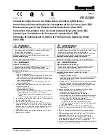
Key Operated Safety Interlock Switch
PK 81590
2 Honeywell
•
MICRO SWITCH Sensing and Control
For application help: call 1-800-537-6945
NOTICE
Tamperproof screws must be used to mount the
switch and key.
Correct functioning of the positive break switch
must be checked during initial installation and
periodically thereafter, noting any wear or drift
which could occur in the application.
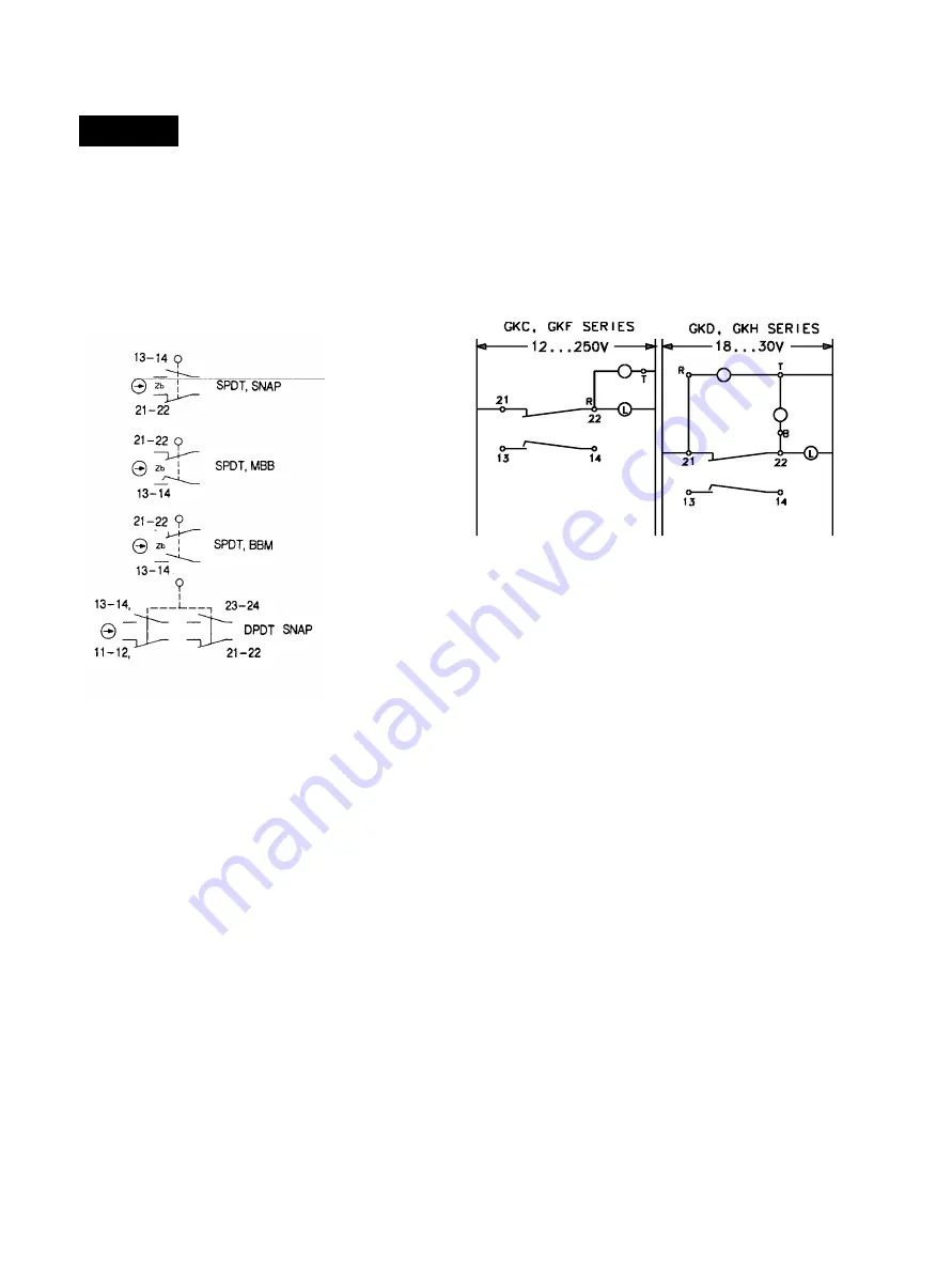
FIGURE 1
BASIC SWITCHES/WIRING
Basic switches are not available as replacement
parts. Circuitries in Figure 1 are shown with the key
inserted. M3 spade terminals, up to 6,35 mm (.25
in.) wide, may be used with all basic switches.
The positive break contact 21-22 and/or 11/12
must be correctly wired into the circuit to ensure
disconnection of the supply, should the switch
mechanism fail.
Before energizing associated equipment, always
check for correct functioning of the switch
mechanism and the positive break mechanism.
After installation and often thereafter, check if any
change or adjustment has been made to the switch
or to the associated installation and, if so, readjust.
INDICATORS (See Figure 2)
Diagrams are shown with key inserted; yellow
indicates door closed, green indicates power on.
Single LED, universal voltage, PLC-compatible,
LED leakage current < 1.5mA
Dual LED, average current draw = 7 mA per LED
Circuits are shown with MBB slow action basic
switch. Any basics shown in Figure 1 may be used
with indicators.
T=Terminal
R=Red wire
B=Black wire
FIGURE 2
YELLOW
GREEN
YELLOW
ROUTINE MAINTENANCE
The safe operation of the machine will depend
upon the safe working of all components and
switches. A regular maintenance routine for the
machine must be established, and that routine
should specifically cover the complete application
involving the switch. To enhance operator safety,
inspect often for any wear on the actuator
mechanism (including the key) operating the switch,
or on the switch itself, or for any appreciable drift in
the operating characteristics. Correct any such
wear or drift as soon as it is detected.
As part of the routine maintenance, attention
must be paid to that part of the machine which is in
any contact with the actuator (key) and to the
switch mounting, to ensure that the actuation is
maintained to the specified travel.
During the routine maintenance, check for correct
functioning of the positive break mechanism for
electrical operation, which shall be carried out by a
qualified person.
Periodic maintenance of the switch will ensure
that continued safe operation of the switch is
maintained. The frequency of maintenance will be
determined by the type of machinery, the frequency
of operation, the application and the local
environment.
Summary of Contents for SYA14 Series
Page 2: ...2 107031 23 EN FR26 GLO 1199 Printed in France This page has been left intentionally blank ...
Page 6: ...6 107031 23 EN FR26 GLO 1199 Printed in France This page has been left intentionally blank ...
Page 26: ...26 107031 23 EN FR26 GLO 1199 Printed in France This page has been left intentionally blank ...
Page 62: ...62 107031 23 EN FR26 GLO 1199 Printed in France This page has been left intentionally blank ...
Page 70: ...70 107031 23 EN FR26 GLO 1199 Printed in France This page has been left intentionally blank ...
Page 76: ...76 107031 23 EN FR26 GLO 1199 Printed in France This page has been left intentionally blank ...
Page 78: ...78 107031 23 EN FR26 GLO 1199 Printed in France This page has been left intentionally blank ...
Page 79: ...107031 23 EN FR26 GLO 1199 Printed in France 79 8 CE Declaration of Conformity ...
Page 80: ...80 107031 23 EN FR26 GLO 1199 Printed in France This page has been left intentionally blank ...
Page 84: ......
Page 158: ......
Page 160: ......
Page 161: ...For application help call 1 800 537 6945 Honeywell MICRO SWITCH Sensing and Control 80 ...
Page 165: ...3 107022 14 EN FR26 GLO 0100 Printed in Germany This page has been left intentionally blank ...
Page 201: ...39 107022 14 EN FR26 GLO 0100 Printed in Germany This page has been left intentionally blank ...
Page 205: ...43 107022 14 EN FR26 GLO 0100 Printed in Germany This page has been left intentionally blank ...
Page 207: ...45 107022 14 EN FR26 GLO 0100 Printed in Germany This page has been left intentionally blank ...
Page 208: ...107022 14 EN FR26 GLO 0100 Printed in Germany 46 9 Declaration of Conformity ...
Page 219: ...11 107006 11 EN FR26 GLO 0300 Printed in Germany This page has been left intentionally blank ...
Page 229: ...21 107006 11 EN FR26 GLO 0300 Printed in Germany This page has been left intentionally blank ...
Page 257: ...49 107006 11 EN FR26 GLO 0300 Printed in Germany This page has been left intentionally blank ...
Page 260: ...107006 11 EN FR26 GLO 0300 Printed in Germany 52 9 3 Declaration of conformity ...
Page 340: ...Safety Perimeter Guarding Installation Manual FF SPS4 Series Safety Perimeter Guarding ...
Page 536: ...2 107004 15 EN FR26 ROW 0899 Printed in France This page has been left intentionally blank ...
Page 538: ...4 107004 15 EN FR26 ROW 0899 Printed in France This page has been left intentionally blank ...
Page 542: ...107004 15 EN FR26 ROW 0899 Printed in France 8 This page has been left intentionally blank ...
Page 620: ...86 107004 15 EN FR26 ROW 0899 Printed in France This page has been left intentionally blank ...
Page 624: ...90 107004 15 EN FR26 ROW 0899 Printed in France This page has been left intentionally blank ...
Page 626: ...92 107004 15 EN FR26 ROW 0899 Printed in France This page has been left intentionally blank ...
Page 627: ...107004 15 EN FR26 ROW 0899 Printed in France 93 8 CE Declaration of Conformity ...
Page 628: ...94 107004 15 EN FR26 ROW 0899 Printed in France This page has been left intentionally blank ...


