107022-14 EN FR26 GLO 0100 Printed in Germany
30
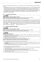
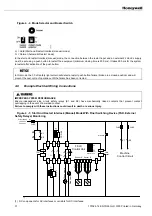
Per the EN 61496 (previously pr EN 50 100 - part 1) standard, the control unit allows installation of lamp indicators as
follows:
•
A green lamp indicator must be connected between the ON terminal and ground. The COM terminal should be
connected to the +24 volt power supply. The ON and COM terminals are located on the control unit circuit board. When
the lamp illuminates (ON), no beams are interrupted, no failures are detected and the output NO contacts are closed.
•
A red lamp must be connected between the OFF terminal and ground. The COM terminal should be connected to the
+24 volt power supply. The OFF and COM terminals are located on the control unit circuit board. When the lamp
illuminates (ON), at least one beam is interrupted, or a failure is detected and the output NO contacts are opened.
Both lamps operate complementarily.
4.6
Connecting The Test Input
POWER APPLIED TO MACHINE CONTROL SYSTEM
Before intervention, turn off and disconnect power from FF-LS Series safety light curtain and machine.
Failure to comply with these instructions could result in death or serious injury.
The test input provides a way to test the functionality of the entire machine safety system. The connection of the test
input to an external 24 Vac/dc supply turns off (opens the NO contacts of the FF-LS safety light curtain) the
equipment even if the beams have not been broken. Once connection between the test input and the external 24
Vac/dc supply is established, ensure that every component of the machine safety control circuitry is operating
correctly.Notes:1)
External 24 Vac/dc supply: 24 Vac/dc, ±25 % (48 to 62 Hz)2) Photocouplers provide an electrical
isolation from the rest of the system3)
Minimum closing time is 100 ms.
4.7
Setting The Mode Of Operation
POWER APPLIED TO MACHINE CONTROL SYSTEM
Before intervention, turn off and disconnect power from FF-LS Series safety light curtain and machine.
Failure to comply with these instructions could result in death or serious injury.
IMPROPER MACHINE RESTART
•
Clearing the sensing zone must not start dangerous machine operation. When restarting the machine operation, a
normal machine control sequence must be used.
•
If electrical power is removed from a machine, its restoration must not initiate dangerous machine operation; a normal
machine control sequence must be used.
•
If a safety light curtain is activated, the machine must NOT be able to restart.
•
A Programmable Logic Controller must NOT be able to override a manual restart function.
Failure to comply with these instructions could result in death or serious injury.
The FF-LS Series safety light curtain may operate in one of two following modes:
•
In the Automatic mode, the FF-LS starts automatically at power up and restarts automatically after any intrusion in the
sensing field.
•
In the Start and Restart Interlock (manual) mode, pushing an external push button (customer supplied) is necessary to
restart the equipment at power up and after any intrusion into the sensing field.
To select the proper mode of operation do the following:
1. Remove the protective plastic covers located on each side of the control unit face plate lid using a small screwdriver
(small recess in covers).
2. Loosen four captive screws securing the face plate lid on the control unit housing and remove the lid.
3. Locate the internal restart mode selector near the buzzer switch (see figure 4-4).
4. Select start and restart interlock (manual) mode (H for Hold) or automatic restart mode (N for Normal) as required.
5. Select buzzer option as required.
6. Reinstall lid, tighten screws and snap the protective plastic covers back in place.
Summary of Contents for SYA14 Series
Page 2: ...2 107031 23 EN FR26 GLO 1199 Printed in France This page has been left intentionally blank ...
Page 6: ...6 107031 23 EN FR26 GLO 1199 Printed in France This page has been left intentionally blank ...
Page 26: ...26 107031 23 EN FR26 GLO 1199 Printed in France This page has been left intentionally blank ...
Page 62: ...62 107031 23 EN FR26 GLO 1199 Printed in France This page has been left intentionally blank ...
Page 70: ...70 107031 23 EN FR26 GLO 1199 Printed in France This page has been left intentionally blank ...
Page 76: ...76 107031 23 EN FR26 GLO 1199 Printed in France This page has been left intentionally blank ...
Page 78: ...78 107031 23 EN FR26 GLO 1199 Printed in France This page has been left intentionally blank ...
Page 79: ...107031 23 EN FR26 GLO 1199 Printed in France 79 8 CE Declaration of Conformity ...
Page 80: ...80 107031 23 EN FR26 GLO 1199 Printed in France This page has been left intentionally blank ...
Page 84: ......
Page 158: ......
Page 160: ......
Page 161: ...For application help call 1 800 537 6945 Honeywell MICRO SWITCH Sensing and Control 80 ...
Page 165: ...3 107022 14 EN FR26 GLO 0100 Printed in Germany This page has been left intentionally blank ...
Page 201: ...39 107022 14 EN FR26 GLO 0100 Printed in Germany This page has been left intentionally blank ...
Page 205: ...43 107022 14 EN FR26 GLO 0100 Printed in Germany This page has been left intentionally blank ...
Page 207: ...45 107022 14 EN FR26 GLO 0100 Printed in Germany This page has been left intentionally blank ...
Page 208: ...107022 14 EN FR26 GLO 0100 Printed in Germany 46 9 Declaration of Conformity ...
Page 219: ...11 107006 11 EN FR26 GLO 0300 Printed in Germany This page has been left intentionally blank ...
Page 229: ...21 107006 11 EN FR26 GLO 0300 Printed in Germany This page has been left intentionally blank ...
Page 257: ...49 107006 11 EN FR26 GLO 0300 Printed in Germany This page has been left intentionally blank ...
Page 260: ...107006 11 EN FR26 GLO 0300 Printed in Germany 52 9 3 Declaration of conformity ...
Page 340: ...Safety Perimeter Guarding Installation Manual FF SPS4 Series Safety Perimeter Guarding ...
Page 536: ...2 107004 15 EN FR26 ROW 0899 Printed in France This page has been left intentionally blank ...
Page 538: ...4 107004 15 EN FR26 ROW 0899 Printed in France This page has been left intentionally blank ...
Page 542: ...107004 15 EN FR26 ROW 0899 Printed in France 8 This page has been left intentionally blank ...
Page 620: ...86 107004 15 EN FR26 ROW 0899 Printed in France This page has been left intentionally blank ...
Page 624: ...90 107004 15 EN FR26 ROW 0899 Printed in France This page has been left intentionally blank ...
Page 626: ...92 107004 15 EN FR26 ROW 0899 Printed in France This page has been left intentionally blank ...
Page 627: ...107004 15 EN FR26 ROW 0899 Printed in France 93 8 CE Declaration of Conformity ...
Page 628: ...94 107004 15 EN FR26 ROW 0899 Printed in France This page has been left intentionally blank ...


