6
107018-04 EN FR26 GLO 1198 Printed in Germany
APPLICATION WARNINGS
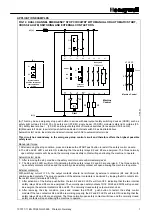
IMPROPER INPUT CONNECTIONS
•
To ensure the highest level of safety, connect two safety device outputs into the two input channels of the
FF-SRS5988 safety module. Then, a cross fault between the two channels will shut down the module.
•
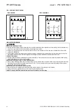
If the safety device provides one safety output only (e.g., a switch driven by a direct acting mechanism like
some GK, GSS, CLS or Emergency Stop push buttons), connect the FF-SRS5988 module as shown in the
single input channel example To avoid any short circuit possibilities on this single input channel, use
conduit to protect wiring and additional protection for the terminal strips inside the machine cabinets.
•
The cable resistance between S11/S12 or S21/S23 should not exceed 68
Ω
and the voltage between
S12/A4 and S22/A4 should not be lower than 21Vdc.
IMPROPER EMERGENCY STOP CONNECTION
•
To ensure maximum safety, connect two normally closed contacts of the Emergency Stop into the input
channel of the FF-SRS5988 module.
IMPROPER AUTOMATIC START MODE IN PERIMETER GUARDING APPLICATIONS
•
If the module is in the automatic start mode, another part of the safety control circuitry must keep the
latched function engaged.
IMPROPER PUSH BUTTON USE (MANUAL START MODE)
•
To ensure maximum safety when using an external start push button, always design the circuitry for
manual start mode (see Mode Setting, page 4).
•
Ensure the location of the manual start function is outside of the danger zone and provides the operator
with a clear view of the zone.
•
For perimeter guarding solutions, the operator should not be able to reach manual start from the danger
zone.
•
A Programmable Logic Controller (PLC) must NOT be able to override a manual start function.
CONTACT WELDING
•
Always protect all safety contacts with correctly rated fuses. These fuses must never exceed the rated FF-
SRS5988 safety output capability to prevent contact welding.
IMPROPER EXTERNAL SAFETY RELAY MONITORING
•
When using additional safety relays (or the FF-SRE Extension module), always connect one normally
closed contact of each relay in series (or 81/82) inside the Final Switching Device (FSD) monitoring loop
circuit (Y1/Y2). This connection will ensure correct operation of the external relays or the Extension
module after each FF-SRS5988 activation.
•
If the FF-SRS5988 is not activated often, the customer is responsible for accomplishing any additional test
procedures of the external safety components. For instance, this testing can be done by removing the
power from the FF-SRS5988 at machine power up every day.
IMPROPER ARC SUPPRESSOR INSTALLATION
•
NEVER install an arc suppressor across the safety output contact of the safety control module.
•
ALWAYS install arc suppressors across the coils of external safety relays.
IMPROPER DOOR MONITORING
•
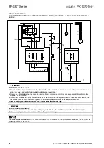
If two safety switches are used to monitor a door’s closed position, connect one safety contact of the first
switch between input S11/S12 and one safety contact of the second switch between S21/S23 of the FF-
SRS 5988 Emergency stop module.
IMPROPER SYSTEM SAFETY LEVEL
•
Several safety components can be connected to a FF-SRS5988 control module. If more than one safety
output is connected to one of the two input channels of the control module, always connect these safety
outputs in series. Parallel wiring of multiple outputs into a single channel can defeat the channel and cause
an unsafe condition.
•
Individually activate and check all of the safety devices connected to a FF-SRS5988 control module to
ensure proper operation.
IMPROPER EMERGENCY STOP PUSH BUTTON
•
The Emergency Stop push button must be designed according to European (EN 418) and US safety
standards (NFPA 19). Under any condition, the Emergency Stop switch must be able to open its contacts
when activated.
LONGER RESPONSE TIME
•
The FF-SRS5988 module will have a longer response time (when the emergency push button is activated)
if the emergency stop push button is connected in series with the power supply of the module. However,
connecting the emergency stop push button to the safety input channels will result in a shorter response
time.
IMPROPER USE OF THE NORMALLY CLOSED OUTPUT CONTACT
•
Use the normally closed output contact (81/82) for monitoring purpose only.
•
Do not use this 81/82 contact in the safety control circuitry of the machine.
Failure to comply with these instructions could result in death or serious injury.
Summary of Contents for SYA14 Series
Page 2: ...2 107031 23 EN FR26 GLO 1199 Printed in France This page has been left intentionally blank ...
Page 6: ...6 107031 23 EN FR26 GLO 1199 Printed in France This page has been left intentionally blank ...
Page 26: ...26 107031 23 EN FR26 GLO 1199 Printed in France This page has been left intentionally blank ...
Page 62: ...62 107031 23 EN FR26 GLO 1199 Printed in France This page has been left intentionally blank ...
Page 70: ...70 107031 23 EN FR26 GLO 1199 Printed in France This page has been left intentionally blank ...
Page 76: ...76 107031 23 EN FR26 GLO 1199 Printed in France This page has been left intentionally blank ...
Page 78: ...78 107031 23 EN FR26 GLO 1199 Printed in France This page has been left intentionally blank ...
Page 79: ...107031 23 EN FR26 GLO 1199 Printed in France 79 8 CE Declaration of Conformity ...
Page 80: ...80 107031 23 EN FR26 GLO 1199 Printed in France This page has been left intentionally blank ...
Page 84: ......
Page 158: ......
Page 160: ......
Page 161: ...For application help call 1 800 537 6945 Honeywell MICRO SWITCH Sensing and Control 80 ...
Page 165: ...3 107022 14 EN FR26 GLO 0100 Printed in Germany This page has been left intentionally blank ...
Page 201: ...39 107022 14 EN FR26 GLO 0100 Printed in Germany This page has been left intentionally blank ...
Page 205: ...43 107022 14 EN FR26 GLO 0100 Printed in Germany This page has been left intentionally blank ...
Page 207: ...45 107022 14 EN FR26 GLO 0100 Printed in Germany This page has been left intentionally blank ...
Page 208: ...107022 14 EN FR26 GLO 0100 Printed in Germany 46 9 Declaration of Conformity ...
Page 219: ...11 107006 11 EN FR26 GLO 0300 Printed in Germany This page has been left intentionally blank ...
Page 229: ...21 107006 11 EN FR26 GLO 0300 Printed in Germany This page has been left intentionally blank ...
Page 257: ...49 107006 11 EN FR26 GLO 0300 Printed in Germany This page has been left intentionally blank ...
Page 260: ...107006 11 EN FR26 GLO 0300 Printed in Germany 52 9 3 Declaration of conformity ...
Page 340: ...Safety Perimeter Guarding Installation Manual FF SPS4 Series Safety Perimeter Guarding ...
Page 536: ...2 107004 15 EN FR26 ROW 0899 Printed in France This page has been left intentionally blank ...
Page 538: ...4 107004 15 EN FR26 ROW 0899 Printed in France This page has been left intentionally blank ...
Page 542: ...107004 15 EN FR26 ROW 0899 Printed in France 8 This page has been left intentionally blank ...
Page 620: ...86 107004 15 EN FR26 ROW 0899 Printed in France This page has been left intentionally blank ...
Page 624: ...90 107004 15 EN FR26 ROW 0899 Printed in France This page has been left intentionally blank ...
Page 626: ...92 107004 15 EN FR26 ROW 0899 Printed in France This page has been left intentionally blank ...
Page 627: ...107004 15 EN FR26 ROW 0899 Printed in France 93 8 CE Declaration of Conformity ...
Page 628: ...94 107004 15 EN FR26 ROW 0899 Printed in France This page has been left intentionally blank ...


