GK Solenoid Safety Interlock Switch
ISSUE 2
PK 81591
For application help: call 1-800-537-6945
Honeywell
•
MICRO SWITCH Sensing and Control 7
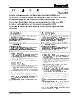
AUXILIARY RELEASE DESCRIPTION (Figure 5)
IMPROPER OPERATION
Do NOT use the auxiliary release for general
maintenance, repair of the machine, or to start and
stop the machine. Use in an emergency situation
only.
Failure to comply with these instructions
could result in death or serious injury.
The auxiliary (or manual) release of the switch
lock mechanism allows the protective guard to be
opened. The auxiliary release is to be used in an
emergency situation only, such as a power failure
when the mechanical lock version is used.
•
Using a screwdriver, rotate the slotted screw as
follows for the listed switch versions to release:
−
Clockwise for Head on Left, Mechanical Lock;
Head on Right, Solenoid Lock.
−
Counterclockwise for Head on Left, Solenoid
Lock; Head on Right, Mechanical Lock.
LOCKING TYPES DESCRIPTION
Mechanical Lock: Occurs by internal spring
force when the protective guard is closed and the
key is inserted. Applying voltage to the solenoid
unlocks this version (or by actuating the auxiliary
release when power failure occurs).
IMPROPER INSTALLATION
Ensure that unintentional power failure on
solenoid lock versions does not cause an unsafe
condition.
Failure to comply with these instructions
could result in death or serious injury.
Solenoid Lock: Occurs by applying voltage to
the solenoid after the protective guard is closed and
the key is inserted. Removing the voltage to the
solenoid unlocks the protective guard.
LOCKING STRENGTH FEATURE
IMPROPER OPERATION
Do not exert over 1000 N (224 lb) extraction force
on actuator key.
Failure to comply with these instructions
could result in death or serious injury.
The switch is equipped with a locking mechanism
to prevent damage to the switch operating head.
This mechanism is designed to withstand 1000 N
(224 lb). If force over 1000 N is exerted on the
actuator key, the mechanism will fracture and
indicate an “open door” condition, requiring
replacement of the entire switch.
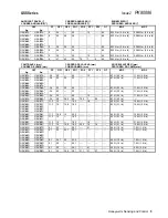
ELECTRICAL RATING
A300 - AC15
Q300 - DC13
Ue (Volts)
Ie (Amps)
Ue (Volts)
Ie (Amps)
120
240
6
3
24
125
250
2.9
.55
.27
Rated Thermal Current (Ith) = 10 A
ENVIRONMENTAL RATING
Sealing
IP68
NEMA 1, 4, 6, 6P, 12, 13
Temperature Range
Operating
Storage
-25
°
to 40
°
C (-13
°
to 104
°
F)
-40
°
to 120
°
C (-40
°
to 248
°
F)
Shock
50 G per IEC 68-2-27
Vibration
10 G per IEC 68-2-6
SPECIFICATIONS
Solenoid Power
12 W
Solenoid Operating
Voltage
12 VDC: +10%, -20%
24 VDC: +10%, -20%
48 VDC: +10%, -20%
24 VAC: +10%, -15%
120 VAC: +10%, -15%
240 VAC: +10%, -15%
Contact Material
Fine Silver
Housing Material
Zinc Die Cast
Mechanical Life
One Million Operations
Summary of Contents for SYA14 Series
Page 2: ...2 107031 23 EN FR26 GLO 1199 Printed in France This page has been left intentionally blank ...
Page 6: ...6 107031 23 EN FR26 GLO 1199 Printed in France This page has been left intentionally blank ...
Page 26: ...26 107031 23 EN FR26 GLO 1199 Printed in France This page has been left intentionally blank ...
Page 62: ...62 107031 23 EN FR26 GLO 1199 Printed in France This page has been left intentionally blank ...
Page 70: ...70 107031 23 EN FR26 GLO 1199 Printed in France This page has been left intentionally blank ...
Page 76: ...76 107031 23 EN FR26 GLO 1199 Printed in France This page has been left intentionally blank ...
Page 78: ...78 107031 23 EN FR26 GLO 1199 Printed in France This page has been left intentionally blank ...
Page 79: ...107031 23 EN FR26 GLO 1199 Printed in France 79 8 CE Declaration of Conformity ...
Page 80: ...80 107031 23 EN FR26 GLO 1199 Printed in France This page has been left intentionally blank ...
Page 84: ......
Page 158: ......
Page 160: ......
Page 161: ...For application help call 1 800 537 6945 Honeywell MICRO SWITCH Sensing and Control 80 ...
Page 165: ...3 107022 14 EN FR26 GLO 0100 Printed in Germany This page has been left intentionally blank ...
Page 201: ...39 107022 14 EN FR26 GLO 0100 Printed in Germany This page has been left intentionally blank ...
Page 205: ...43 107022 14 EN FR26 GLO 0100 Printed in Germany This page has been left intentionally blank ...
Page 207: ...45 107022 14 EN FR26 GLO 0100 Printed in Germany This page has been left intentionally blank ...
Page 208: ...107022 14 EN FR26 GLO 0100 Printed in Germany 46 9 Declaration of Conformity ...
Page 219: ...11 107006 11 EN FR26 GLO 0300 Printed in Germany This page has been left intentionally blank ...
Page 229: ...21 107006 11 EN FR26 GLO 0300 Printed in Germany This page has been left intentionally blank ...
Page 257: ...49 107006 11 EN FR26 GLO 0300 Printed in Germany This page has been left intentionally blank ...
Page 260: ...107006 11 EN FR26 GLO 0300 Printed in Germany 52 9 3 Declaration of conformity ...
Page 340: ...Safety Perimeter Guarding Installation Manual FF SPS4 Series Safety Perimeter Guarding ...
Page 536: ...2 107004 15 EN FR26 ROW 0899 Printed in France This page has been left intentionally blank ...
Page 538: ...4 107004 15 EN FR26 ROW 0899 Printed in France This page has been left intentionally blank ...
Page 542: ...107004 15 EN FR26 ROW 0899 Printed in France 8 This page has been left intentionally blank ...
Page 620: ...86 107004 15 EN FR26 ROW 0899 Printed in France This page has been left intentionally blank ...
Page 624: ...90 107004 15 EN FR26 ROW 0899 Printed in France This page has been left intentionally blank ...
Page 626: ...92 107004 15 EN FR26 ROW 0899 Printed in France This page has been left intentionally blank ...
Page 627: ...107004 15 EN FR26 ROW 0899 Printed in France 93 8 CE Declaration of Conformity ...
Page 628: ...94 107004 15 EN FR26 ROW 0899 Printed in France This page has been left intentionally blank ...


