37
107022-14 EN FR26 GLO 0100 Printed in Germany
If a protective safety equipment (FF-LS safety light curtains or machine safety control equipment monitored by the FF-LS)
failure occurs during self-check or test input, the protective safety equipment is locked in an OFF condition. This OFF
condition cannot be defeated by turning the power supply voltage OFF and ON.
Table 5-4 Troubleshooting Chart
Failure
Possible cause
Inspect and repair
•
Sensing field is clear, but the protective
safety equipment will not release after
actuation of an external reset push
button switch.
•
Green LED indicator is illuminated.
•
Open circuit between output relays
and machine control circuitry.
•
Inspect terminal wiring and, if
necessary, repair wiring.
•
Blown fuse at output relay terminals.
•
Replace fuse.
•
Sensing field is clear, but the protective
safety equipment will not release after
actuation of an external reset push
button switch.
•
Red LED indicator is illuminated.
•
Open circuit between both or one of
the sensing units and the control
unit.
•
Ensure correct terminal polarity
and proper cable connection
between the sensing and control
units.
•
Translucent surface of sensing units
are contaminated.
•
Clean surface.
•
Sensing unit is defective.
•
Replace sensing unit (matched
pair).
•
Faulty reset pushbutton or open
circuit.
•
Replace reset pushbutton or repair
wiring.
•
Sensing field is clear, but the protective
safety equipment will not release after
actuation of an external reset push
button switch.
•
No LED indicator is illuminated.
•
No supply voltage to the control
unit.
•
Inspect terminal wiring and, if
necessary, repair wiring.
•
Blown fuse at supply voltage
terminal.
•
Replace fuse. See fuse
replacement. (5.4.1)
•
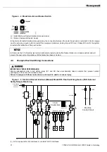
During normal operation the red LED 5,
located near microprocessor on circuit
board in control unit (see figure 5-2),
pulses (illuminates) every 3 seconds.
•
If there is no release when the sensing
field is clear, the red LED 5 may:
•
Illuminate continuously
•
Faulty synchronization
•
Replace control unit.
•
Flicker one time
•
Faulty self test
•
Replace control unit.
•
Flicker two times
•
Faulty communication
•
Replace matched sensor units.
•
Visually inspect cable pair and
replace if required.
•
Flicker three times
•
Faulty communication sensor A
•
Visually inspect sensor cable A
and replace if required.
•
Flicker four times
•
Faulty communication sensor B
•
Visually inspect sensor cable B
and replace if required.
•
Flicker five times
•
Faulty installation parameters
•
Visually inspect compatibility of
sensor and control unit
components. Ensure the beam
number labels on all of the
components are the same.
Summary of Contents for SYA14 Series
Page 2: ...2 107031 23 EN FR26 GLO 1199 Printed in France This page has been left intentionally blank ...
Page 6: ...6 107031 23 EN FR26 GLO 1199 Printed in France This page has been left intentionally blank ...
Page 26: ...26 107031 23 EN FR26 GLO 1199 Printed in France This page has been left intentionally blank ...
Page 62: ...62 107031 23 EN FR26 GLO 1199 Printed in France This page has been left intentionally blank ...
Page 70: ...70 107031 23 EN FR26 GLO 1199 Printed in France This page has been left intentionally blank ...
Page 76: ...76 107031 23 EN FR26 GLO 1199 Printed in France This page has been left intentionally blank ...
Page 78: ...78 107031 23 EN FR26 GLO 1199 Printed in France This page has been left intentionally blank ...
Page 79: ...107031 23 EN FR26 GLO 1199 Printed in France 79 8 CE Declaration of Conformity ...
Page 80: ...80 107031 23 EN FR26 GLO 1199 Printed in France This page has been left intentionally blank ...
Page 84: ......
Page 158: ......
Page 160: ......
Page 161: ...For application help call 1 800 537 6945 Honeywell MICRO SWITCH Sensing and Control 80 ...
Page 165: ...3 107022 14 EN FR26 GLO 0100 Printed in Germany This page has been left intentionally blank ...
Page 201: ...39 107022 14 EN FR26 GLO 0100 Printed in Germany This page has been left intentionally blank ...
Page 205: ...43 107022 14 EN FR26 GLO 0100 Printed in Germany This page has been left intentionally blank ...
Page 207: ...45 107022 14 EN FR26 GLO 0100 Printed in Germany This page has been left intentionally blank ...
Page 208: ...107022 14 EN FR26 GLO 0100 Printed in Germany 46 9 Declaration of Conformity ...
Page 219: ...11 107006 11 EN FR26 GLO 0300 Printed in Germany This page has been left intentionally blank ...
Page 229: ...21 107006 11 EN FR26 GLO 0300 Printed in Germany This page has been left intentionally blank ...
Page 257: ...49 107006 11 EN FR26 GLO 0300 Printed in Germany This page has been left intentionally blank ...
Page 260: ...107006 11 EN FR26 GLO 0300 Printed in Germany 52 9 3 Declaration of conformity ...
Page 340: ...Safety Perimeter Guarding Installation Manual FF SPS4 Series Safety Perimeter Guarding ...
Page 536: ...2 107004 15 EN FR26 ROW 0899 Printed in France This page has been left intentionally blank ...
Page 538: ...4 107004 15 EN FR26 ROW 0899 Printed in France This page has been left intentionally blank ...
Page 542: ...107004 15 EN FR26 ROW 0899 Printed in France 8 This page has been left intentionally blank ...
Page 620: ...86 107004 15 EN FR26 ROW 0899 Printed in France This page has been left intentionally blank ...
Page 624: ...90 107004 15 EN FR26 ROW 0899 Printed in France This page has been left intentionally blank ...
Page 626: ...92 107004 15 EN FR26 ROW 0899 Printed in France This page has been left intentionally blank ...
Page 627: ...107004 15 EN FR26 ROW 0899 Printed in France 93 8 CE Declaration of Conformity ...
Page 628: ...94 107004 15 EN FR26 ROW 0899 Printed in France This page has been left intentionally blank ...


