iv Honeywell
•
PK 107007-01 EN FR26 GLO 0298 Printed in France
For application help: see Warranty Information
Table of Contents (cont’d)
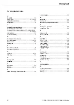
Serial Connection of Several Safety Mats ....................................................................... 24
Area Controlled By Several Safety Mats Via A Single Control Unit............................. 24
Determining The Number Of Safety Mats Controlled By A Control Unit...................... 26
Area Controlled By Several Safety Mats Run By Several Control Units...................... 26
Mounting Dimensions (for reference only)....................................................................... 27
Connections and Setup......................................................................................................... 31
Overview .......................................................................................................................... 31
Fiber Optic Connections .................................................................................................. 32
Fiber Optic Cable Connection To The Control Unit ..................................................... 32
ST Connector With The Cable-To-Cable Connector ................................................... 33
Fiber Optic Cable Connection To The Connecting Box............................................... 33
Electrical Connections ..................................................................................................... 34
Overview ...................................................................................................................... 34
Power Supply Wiring.................................................................................................... 35
Machine Stop Contacts (X1 and X2)................................................................................ 36
Permanent Self-checking (Monitoring)......................................................................... 36
Protection of Relay Contacts (X1 and X2) ................................................................... 36
Final Switching Devices (FSD) K1 and K2................................................................... 37
Internal Auxiliary Contacts X1 and X2 (see figure 3-4).................................................... 38
Final Switching Device (FSD) Monitoring ........................................................................ 39
Overview ...................................................................................................................... 39
Test input ......................................................................................................................... 40
Contact Status ............................................................................................................. 40
Physical Configuration and Wiring Diagram Examples.................................................... 41
Setup................................................................................................................................ 46
Excess Gain Adjustment After Installation................................................................... 46
Indicator Status ............................................................................................................ 48
Sensing Threshold Indicator (see figure 3-15)............................................................. 48
Excess Gain Adjustment During Operation ................................................................. 49
Inspection and Maintenance................................................................................................. 51
Overview .......................................................................................................................... 51
Operational Test .............................................................................................................. 51
Inspection......................................................................................................................... 52
Important Information................................................................................................... 52
Maintenance .................................................................................................................... 53
Fuse Replacement....................................................................................................... 53
Indicator Status and Corrective Actions........................................................................... 54
Troubleshooting Flow Diagram (Sheet 1 of 2) ................................................................. 55
Troubleshooting Flow Diagram (Sheet 2 of 2) ................................................................. 56
Summary of Contents for SYA14 Series
Page 2: ...2 107031 23 EN FR26 GLO 1199 Printed in France This page has been left intentionally blank ...
Page 6: ...6 107031 23 EN FR26 GLO 1199 Printed in France This page has been left intentionally blank ...
Page 26: ...26 107031 23 EN FR26 GLO 1199 Printed in France This page has been left intentionally blank ...
Page 62: ...62 107031 23 EN FR26 GLO 1199 Printed in France This page has been left intentionally blank ...
Page 70: ...70 107031 23 EN FR26 GLO 1199 Printed in France This page has been left intentionally blank ...
Page 76: ...76 107031 23 EN FR26 GLO 1199 Printed in France This page has been left intentionally blank ...
Page 78: ...78 107031 23 EN FR26 GLO 1199 Printed in France This page has been left intentionally blank ...
Page 79: ...107031 23 EN FR26 GLO 1199 Printed in France 79 8 CE Declaration of Conformity ...
Page 80: ...80 107031 23 EN FR26 GLO 1199 Printed in France This page has been left intentionally blank ...
Page 84: ......
Page 158: ......
Page 160: ......
Page 161: ...For application help call 1 800 537 6945 Honeywell MICRO SWITCH Sensing and Control 80 ...
Page 165: ...3 107022 14 EN FR26 GLO 0100 Printed in Germany This page has been left intentionally blank ...
Page 201: ...39 107022 14 EN FR26 GLO 0100 Printed in Germany This page has been left intentionally blank ...
Page 205: ...43 107022 14 EN FR26 GLO 0100 Printed in Germany This page has been left intentionally blank ...
Page 207: ...45 107022 14 EN FR26 GLO 0100 Printed in Germany This page has been left intentionally blank ...
Page 208: ...107022 14 EN FR26 GLO 0100 Printed in Germany 46 9 Declaration of Conformity ...
Page 219: ...11 107006 11 EN FR26 GLO 0300 Printed in Germany This page has been left intentionally blank ...
Page 229: ...21 107006 11 EN FR26 GLO 0300 Printed in Germany This page has been left intentionally blank ...
Page 257: ...49 107006 11 EN FR26 GLO 0300 Printed in Germany This page has been left intentionally blank ...
Page 260: ...107006 11 EN FR26 GLO 0300 Printed in Germany 52 9 3 Declaration of conformity ...
Page 340: ...Safety Perimeter Guarding Installation Manual FF SPS4 Series Safety Perimeter Guarding ...
Page 536: ...2 107004 15 EN FR26 ROW 0899 Printed in France This page has been left intentionally blank ...
Page 538: ...4 107004 15 EN FR26 ROW 0899 Printed in France This page has been left intentionally blank ...
Page 542: ...107004 15 EN FR26 ROW 0899 Printed in France 8 This page has been left intentionally blank ...
Page 620: ...86 107004 15 EN FR26 ROW 0899 Printed in France This page has been left intentionally blank ...
Page 624: ...90 107004 15 EN FR26 ROW 0899 Printed in France This page has been left intentionally blank ...
Page 626: ...92 107004 15 EN FR26 ROW 0899 Printed in France This page has been left intentionally blank ...
Page 627: ...107004 15 EN FR26 ROW 0899 Printed in France 93 8 CE Declaration of Conformity ...
Page 628: ...94 107004 15 EN FR26 ROW 0899 Printed in France This page has been left intentionally blank ...


