Installation Instructions for the
ISSUE 3
50FY Series Hall Effect
Door Interrupt System, EN954 Category III
PK 80391
MICRO SWITCH Sensing and Control
IMPROPER INSTALLATION
•
This product is designed to conform to the
technical requirements of EN954 Category III and
ANSI B11.19-1990. To ensure compliance with
these requirements, 50FY41 sensors MUST be
used with the FYQLA1-140R-3 logic amplifier.
•
Consult with local safety agency and its
requirements when designing a machine control
link, interface and all control elements that affect
safety.
•
Strictly adhere to all installation instructions.
Failure to comply with these instructions could
result in death or serious injury.
GENERAL
The 50FY Series Hall Effect Door Interrupt
System is a non-contact, magnetic actuation system
consisting of three devices: a sensor, a magnetic
actuator and a logic amplifier.
The sensor contains two Hall Effect integrated
circuits that are connected independently. Both
circuits must turn on simultaneously to produce an
output.
The magnet actuator has a keyed magnetic field
that must match the sensor to operate correctly.
When exposed to this keyed magnetic field and
properly aligned, the sensor responds with an
output.
The logic amplifier contains a logic input circuit
card and controls a relay output. The input circuit
will accept up to six sensors. When all of the
connected sensors are actuated, the logic circuit will
close the relay contacts. If any of the connected
sensors are turned off, the logic circuit will open the
relay contacts.
INSTALLATION INSTRUCTIONS
Step 1 - Mount and align 50FY sensor as
follows:
IMPROPER ALIGNMENT
Ensure the alignment of the sensor and magnetic
actuator face each other and are aligned for proper
operation. A 10 mm (0.39 in) separation distance
will cause an OFF condition, regardless of offset
distance.
Failure to comply with these instructions could
result in death or serious injury.
•
Mount and align the sensor and magnetic actuator
(see Mounting Dimensions, Nominal Sensing
Distance, and Offset vs. Distance) within the
allowable offset.
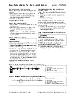
NOMINAL SENSING DISTANCE mm (in)
Offset
Distance
Zero
2,5 (0.100)
3,8 (0.150)
1,3 (0.050)
7,5 (0.300)
Zero
OFFSET VS DISTANCE
Summary of Contents for SYA14 Series
Page 2: ...2 107031 23 EN FR26 GLO 1199 Printed in France This page has been left intentionally blank ...
Page 6: ...6 107031 23 EN FR26 GLO 1199 Printed in France This page has been left intentionally blank ...
Page 26: ...26 107031 23 EN FR26 GLO 1199 Printed in France This page has been left intentionally blank ...
Page 62: ...62 107031 23 EN FR26 GLO 1199 Printed in France This page has been left intentionally blank ...
Page 70: ...70 107031 23 EN FR26 GLO 1199 Printed in France This page has been left intentionally blank ...
Page 76: ...76 107031 23 EN FR26 GLO 1199 Printed in France This page has been left intentionally blank ...
Page 78: ...78 107031 23 EN FR26 GLO 1199 Printed in France This page has been left intentionally blank ...
Page 79: ...107031 23 EN FR26 GLO 1199 Printed in France 79 8 CE Declaration of Conformity ...
Page 80: ...80 107031 23 EN FR26 GLO 1199 Printed in France This page has been left intentionally blank ...
Page 84: ......
Page 158: ......
Page 160: ......
Page 161: ...For application help call 1 800 537 6945 Honeywell MICRO SWITCH Sensing and Control 80 ...
Page 165: ...3 107022 14 EN FR26 GLO 0100 Printed in Germany This page has been left intentionally blank ...
Page 201: ...39 107022 14 EN FR26 GLO 0100 Printed in Germany This page has been left intentionally blank ...
Page 205: ...43 107022 14 EN FR26 GLO 0100 Printed in Germany This page has been left intentionally blank ...
Page 207: ...45 107022 14 EN FR26 GLO 0100 Printed in Germany This page has been left intentionally blank ...
Page 208: ...107022 14 EN FR26 GLO 0100 Printed in Germany 46 9 Declaration of Conformity ...
Page 219: ...11 107006 11 EN FR26 GLO 0300 Printed in Germany This page has been left intentionally blank ...
Page 229: ...21 107006 11 EN FR26 GLO 0300 Printed in Germany This page has been left intentionally blank ...
Page 257: ...49 107006 11 EN FR26 GLO 0300 Printed in Germany This page has been left intentionally blank ...
Page 260: ...107006 11 EN FR26 GLO 0300 Printed in Germany 52 9 3 Declaration of conformity ...
Page 340: ...Safety Perimeter Guarding Installation Manual FF SPS4 Series Safety Perimeter Guarding ...
Page 536: ...2 107004 15 EN FR26 ROW 0899 Printed in France This page has been left intentionally blank ...
Page 538: ...4 107004 15 EN FR26 ROW 0899 Printed in France This page has been left intentionally blank ...
Page 542: ...107004 15 EN FR26 ROW 0899 Printed in France 8 This page has been left intentionally blank ...
Page 620: ...86 107004 15 EN FR26 ROW 0899 Printed in France This page has been left intentionally blank ...
Page 624: ...90 107004 15 EN FR26 ROW 0899 Printed in France This page has been left intentionally blank ...
Page 626: ...92 107004 15 EN FR26 ROW 0899 Printed in France This page has been left intentionally blank ...
Page 627: ...107004 15 EN FR26 ROW 0899 Printed in France 93 8 CE Declaration of Conformity ...
Page 628: ...94 107004 15 EN FR26 ROW 0899 Printed in France This page has been left intentionally blank ...


