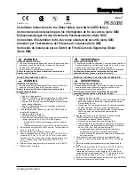
GK Solenoid Safety Interlock Switch
ISSUE 2
PK 81591
For application help: call 1-800-537-6945
Honeywell
•
MICRO SWITCH Sensing and Control 5
Step 3 - Wire switch:
IMPROPER INSTALLATION
Strictly adhere to all electrical connection
instructions.
Failure to comply with these instructions
could result in death or serious injury.
•
Refer to Figures 5, 6, 7, and 8 for 1NC - 1NO
wiring configuration.
•
M3 spade terminals up to 6,35 mm (0.25 in) wide
may be used with contact block should additional
wiring be required.
•
Solenoid is prewired to the terminal strip.
•
Torque wire connections as follows:
−
Torque connector to secure cable to switch
enclosure (if required): 1,8-2,2 N-m
(16-10 in-lb).
−
Torque switch terminal screws: 0,8-1,0 N-m
(7-9 in-lb) M3.
−
Torque ground screw: 0,8-1,0 N-m (7-9 in-lb)
M3.
Step 4 - Seal conduit entry:
•
Seal with Teflon tape or pipe sealant.
•
If connector is used to secure cable to switch
enclosure, torque connector to 1,8-2,2 N-m (16-
19 in-lb).
•
Plug any unused conduit entry (plug included).
Seal with Teflon tape or pipe sealant.
PERFORM MECHANICAL FUNCTION TEST
•
Open and close protective guard several times to
ensure key slides easily into switch head.
PERFORM ELECTRICAL FUNCTION TEST
•
Close the protective guard and ensure switch
locks. It must not be possible to open the
protective guard when hazardous motion is
present.
•
After the switch unlocks, open the protective
guard. The hazardous motion must not start
when the protective guard is unlocked or open.
MAINTENANCE AND INSPECTION
IMPROPER MAINTENANCE
•
Strictly adhere to all maintenance and inspection
instructions.
•
If wear, damage, or contamination is found,
replace the entire switch and key assembly. Do
not replace individual parts.
•
Do not exceed one million switching operations.
Failure to comply with these instructions
could result in death or serious injury.
Maintenance frequency will be determined by the
type of machinery, the frequency of operation, the
application, and the local environment. Inspect for
and correct the following:
ROUTINE MAINTENANCE CHECKLIST
√
Switch and key mounting. Mounting should
be secure and permanent.
√
Switch and key alignment. The key should
move freely with no jamming in the switch
during operation.
√
Wear or mechanical damage.
√
Correct electrical and mechanical switching
function.
√
Switch sealing. Ensure there are no liquids
in switch enclosure.
√
The complete safety switch assembly must
be replaced after one million switch
operations.
Summary of Contents for SYA14 Series
Page 2: ...2 107031 23 EN FR26 GLO 1199 Printed in France This page has been left intentionally blank ...
Page 6: ...6 107031 23 EN FR26 GLO 1199 Printed in France This page has been left intentionally blank ...
Page 26: ...26 107031 23 EN FR26 GLO 1199 Printed in France This page has been left intentionally blank ...
Page 62: ...62 107031 23 EN FR26 GLO 1199 Printed in France This page has been left intentionally blank ...
Page 70: ...70 107031 23 EN FR26 GLO 1199 Printed in France This page has been left intentionally blank ...
Page 76: ...76 107031 23 EN FR26 GLO 1199 Printed in France This page has been left intentionally blank ...
Page 78: ...78 107031 23 EN FR26 GLO 1199 Printed in France This page has been left intentionally blank ...
Page 79: ...107031 23 EN FR26 GLO 1199 Printed in France 79 8 CE Declaration of Conformity ...
Page 80: ...80 107031 23 EN FR26 GLO 1199 Printed in France This page has been left intentionally blank ...
Page 84: ......
Page 158: ......
Page 160: ......
Page 161: ...For application help call 1 800 537 6945 Honeywell MICRO SWITCH Sensing and Control 80 ...
Page 165: ...3 107022 14 EN FR26 GLO 0100 Printed in Germany This page has been left intentionally blank ...
Page 201: ...39 107022 14 EN FR26 GLO 0100 Printed in Germany This page has been left intentionally blank ...
Page 205: ...43 107022 14 EN FR26 GLO 0100 Printed in Germany This page has been left intentionally blank ...
Page 207: ...45 107022 14 EN FR26 GLO 0100 Printed in Germany This page has been left intentionally blank ...
Page 208: ...107022 14 EN FR26 GLO 0100 Printed in Germany 46 9 Declaration of Conformity ...
Page 219: ...11 107006 11 EN FR26 GLO 0300 Printed in Germany This page has been left intentionally blank ...
Page 229: ...21 107006 11 EN FR26 GLO 0300 Printed in Germany This page has been left intentionally blank ...
Page 257: ...49 107006 11 EN FR26 GLO 0300 Printed in Germany This page has been left intentionally blank ...
Page 260: ...107006 11 EN FR26 GLO 0300 Printed in Germany 52 9 3 Declaration of conformity ...
Page 340: ...Safety Perimeter Guarding Installation Manual FF SPS4 Series Safety Perimeter Guarding ...
Page 536: ...2 107004 15 EN FR26 ROW 0899 Printed in France This page has been left intentionally blank ...
Page 538: ...4 107004 15 EN FR26 ROW 0899 Printed in France This page has been left intentionally blank ...
Page 542: ...107004 15 EN FR26 ROW 0899 Printed in France 8 This page has been left intentionally blank ...
Page 620: ...86 107004 15 EN FR26 ROW 0899 Printed in France This page has been left intentionally blank ...
Page 624: ...90 107004 15 EN FR26 ROW 0899 Printed in France This page has been left intentionally blank ...
Page 626: ...92 107004 15 EN FR26 ROW 0899 Printed in France This page has been left intentionally blank ...
Page 627: ...107004 15 EN FR26 ROW 0899 Printed in France 93 8 CE Declaration of Conformity ...
Page 628: ...94 107004 15 EN FR26 ROW 0899 Printed in France This page has been left intentionally blank ...


