107006-11 EN FR26 GLO 0300 Printed in Germany
26
❚
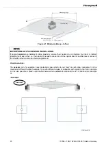
Mounting the FF-SE :
IMPROPER INSTALLATION ENVIRONMENT
Before mounting the sensor, ensure the machine is switched off and all danger is eliminated.
Failure to comply with these instructions could result in death or serious injury.
1. Secure the FF-SE to the mounting surface with its screws, washers and lock washers.
2. Align
the
sensor, then tighten the mounting hardware.
3. Use a bubble level if necessary.
4. Follow Electrical connections section 5
You will find the dimensions in the Appendix 9
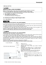
4.5 Statutory mounting and operating provisions
4.5.1 Safety distances
IMPROPER APPLICATION OF FF-SE LASER SCANNER
•
A safety laser scanner may be used as primary protection for machines where the movement of the functional
parts can be interrupted at any time during the dangerous cycle.
• A safety laser scanner may be used as primary protection for machines where the control circuit has been
designed so that a fault in one component does not result in any risk.
• Cancellation of the safety laser scanner stop signal must not cause the restart of the moving parts. The
function to restart may only be initiated by means of a control designed for this purpose.
Failure to comply with these instructions will result in death or serious injury.
IMPROPER APPLICATION OF FF-SE LASER SCANNER
• If the FF-SE is OFF, the machine must be switched off.
• The maximum value of the machine stop time, including the FF-SE’s response time must be short enough so
that no object can penetrate the danger area before the dangerous movement is stopped.
• The safety distance S between the protection area and the dangerous zone must be less than the maximum
sensing distance. The calculation of the distance of the protection area must take into account the response time
of the FF-SE, the stopping time of the machine with regard to the penetration velocity of an object or a person
and an error margin.
In Europe, it must be calculated according to paragraph 6.2 of EN 999.
Failure to comply with these instructions could result in death or serious injury.
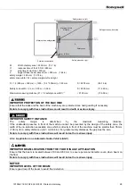
European Standards :
S
≥
1.6 (t1 + t2) + (1200 - 0.4 H) + E
Where :
•
S
=
distance
(in
mm)
•
1,6 =
penetration velocity (in mm/ms)
•
t1 =
response time of the FF-SE (see section Technical
specifications)
•
t2 =
stopping time of the machine (in ms) ; i.e. the time interval
necessary to stop the machine, after the protection device
has emitted the stop signal
•
H
=
height of the beam from the ground, 300
≤
H
≤
1000 mm
•
E
=
maximum error in measurement (see chapter 4.5.2)
•
Install hard guarding on the sides and back of the
machine.
•
Install hard guarding fences on all sides, or set up
the zone to ensure a « S » safety distance in all
directions.
Summary of Contents for SYA14 Series
Page 2: ...2 107031 23 EN FR26 GLO 1199 Printed in France This page has been left intentionally blank ...
Page 6: ...6 107031 23 EN FR26 GLO 1199 Printed in France This page has been left intentionally blank ...
Page 26: ...26 107031 23 EN FR26 GLO 1199 Printed in France This page has been left intentionally blank ...
Page 62: ...62 107031 23 EN FR26 GLO 1199 Printed in France This page has been left intentionally blank ...
Page 70: ...70 107031 23 EN FR26 GLO 1199 Printed in France This page has been left intentionally blank ...
Page 76: ...76 107031 23 EN FR26 GLO 1199 Printed in France This page has been left intentionally blank ...
Page 78: ...78 107031 23 EN FR26 GLO 1199 Printed in France This page has been left intentionally blank ...
Page 79: ...107031 23 EN FR26 GLO 1199 Printed in France 79 8 CE Declaration of Conformity ...
Page 80: ...80 107031 23 EN FR26 GLO 1199 Printed in France This page has been left intentionally blank ...
Page 84: ......
Page 158: ......
Page 160: ......
Page 161: ...For application help call 1 800 537 6945 Honeywell MICRO SWITCH Sensing and Control 80 ...
Page 165: ...3 107022 14 EN FR26 GLO 0100 Printed in Germany This page has been left intentionally blank ...
Page 201: ...39 107022 14 EN FR26 GLO 0100 Printed in Germany This page has been left intentionally blank ...
Page 205: ...43 107022 14 EN FR26 GLO 0100 Printed in Germany This page has been left intentionally blank ...
Page 207: ...45 107022 14 EN FR26 GLO 0100 Printed in Germany This page has been left intentionally blank ...
Page 208: ...107022 14 EN FR26 GLO 0100 Printed in Germany 46 9 Declaration of Conformity ...
Page 219: ...11 107006 11 EN FR26 GLO 0300 Printed in Germany This page has been left intentionally blank ...
Page 229: ...21 107006 11 EN FR26 GLO 0300 Printed in Germany This page has been left intentionally blank ...
Page 257: ...49 107006 11 EN FR26 GLO 0300 Printed in Germany This page has been left intentionally blank ...
Page 260: ...107006 11 EN FR26 GLO 0300 Printed in Germany 52 9 3 Declaration of conformity ...
Page 340: ...Safety Perimeter Guarding Installation Manual FF SPS4 Series Safety Perimeter Guarding ...
Page 536: ...2 107004 15 EN FR26 ROW 0899 Printed in France This page has been left intentionally blank ...
Page 538: ...4 107004 15 EN FR26 ROW 0899 Printed in France This page has been left intentionally blank ...
Page 542: ...107004 15 EN FR26 ROW 0899 Printed in France 8 This page has been left intentionally blank ...
Page 620: ...86 107004 15 EN FR26 ROW 0899 Printed in France This page has been left intentionally blank ...
Page 624: ...90 107004 15 EN FR26 ROW 0899 Printed in France This page has been left intentionally blank ...
Page 626: ...92 107004 15 EN FR26 ROW 0899 Printed in France This page has been left intentionally blank ...
Page 627: ...107004 15 EN FR26 ROW 0899 Printed in France 93 8 CE Declaration of Conformity ...
Page 628: ...94 107004 15 EN FR26 ROW 0899 Printed in France This page has been left intentionally blank ...


