107018-04 EN FR26 GLO 1198 Printed in Germany
9
APPLICATION EXAMPLES (continued)
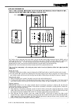
FIG. 12.: DUAL-CHANNEL SAFETY DOOR MONITORING
(WITH CROSS-FAULT MONITORING, AUTOMATIC START MODE)
L1
Honeywell
FF-SRS 5988
N
Y1 Y2
X1 X2
S33
S11
A3
(+)
S34
(B)
A4
(-)
Machine
Control
Sliding guard
(closed position)
closed
open
Fuse
Fuses
Power
GENERAL DESCRIPTION OF SAFETY DOOR APPLICATIONS
Protective gates are designed to limit or block access to the moving parts of dangerous machinery. These
gates can be equipped with locking or interlocking devices, usually safety limit switches or any other safety
sensors/switches.
The FF-SRS5988 Emergency Stop module monitors the status of these safety sensor positions. When the
protective gate is open, the initiation of dangerous motion is prevented. When the door is closed again, the
next machine cycle can start, but only after initiating a manual restart sequence.
FUNCTIONAL DESCRIPTION
After opening the door, the two external safety switch contacts S1 and S2 will open (as illustrated above) and
the two internal safety relays K2 and K3 will de-energize. The normally open safety outputs 13/14.. 63/64 will
open relaying the stop condition to the machine control circuitry. After closing the door, S1 and S2 close and
the internal relays K2 and K3 will energize. The six normally open safety contacts will close and an external
manual restart sequence may then be initiated (allowing the machine to operate).
IMPORTANT NOTICES
SAFETY LIMIT SWITCH SEQUENCE
•
In order to let the module restart automatically, safety limit switch S1 must not close before switch S2. The
FF-SRS5988 will only restart after the two input channels have been opened and then closed (an
activation).
•
In the manual start mode the safety limit switch sequence has no impact.
•
In the manual start mode, closing the start push button will immediately close the normally open contacts of
the safety control module and initiate a machine start cycle. The push button must be released before the
next start cycle is allowed. This will prevent automatic start in case the push button is broken in the closed
position.
•
The cable resistance between S11/S12 and S21/S23 must be less than 68
Ω
(ohms) for correct operation
of the safety control module.
•
A minimum of 21 vdc must be present between each channel input (S11/S12 and S21/S23) to ensure the
correct detection of sensor(s) outputs status.
Summary of Contents for SYA14 Series
Page 2: ...2 107031 23 EN FR26 GLO 1199 Printed in France This page has been left intentionally blank ...
Page 6: ...6 107031 23 EN FR26 GLO 1199 Printed in France This page has been left intentionally blank ...
Page 26: ...26 107031 23 EN FR26 GLO 1199 Printed in France This page has been left intentionally blank ...
Page 62: ...62 107031 23 EN FR26 GLO 1199 Printed in France This page has been left intentionally blank ...
Page 70: ...70 107031 23 EN FR26 GLO 1199 Printed in France This page has been left intentionally blank ...
Page 76: ...76 107031 23 EN FR26 GLO 1199 Printed in France This page has been left intentionally blank ...
Page 78: ...78 107031 23 EN FR26 GLO 1199 Printed in France This page has been left intentionally blank ...
Page 79: ...107031 23 EN FR26 GLO 1199 Printed in France 79 8 CE Declaration of Conformity ...
Page 80: ...80 107031 23 EN FR26 GLO 1199 Printed in France This page has been left intentionally blank ...
Page 84: ......
Page 158: ......
Page 160: ......
Page 161: ...For application help call 1 800 537 6945 Honeywell MICRO SWITCH Sensing and Control 80 ...
Page 165: ...3 107022 14 EN FR26 GLO 0100 Printed in Germany This page has been left intentionally blank ...
Page 201: ...39 107022 14 EN FR26 GLO 0100 Printed in Germany This page has been left intentionally blank ...
Page 205: ...43 107022 14 EN FR26 GLO 0100 Printed in Germany This page has been left intentionally blank ...
Page 207: ...45 107022 14 EN FR26 GLO 0100 Printed in Germany This page has been left intentionally blank ...
Page 208: ...107022 14 EN FR26 GLO 0100 Printed in Germany 46 9 Declaration of Conformity ...
Page 219: ...11 107006 11 EN FR26 GLO 0300 Printed in Germany This page has been left intentionally blank ...
Page 229: ...21 107006 11 EN FR26 GLO 0300 Printed in Germany This page has been left intentionally blank ...
Page 257: ...49 107006 11 EN FR26 GLO 0300 Printed in Germany This page has been left intentionally blank ...
Page 260: ...107006 11 EN FR26 GLO 0300 Printed in Germany 52 9 3 Declaration of conformity ...
Page 340: ...Safety Perimeter Guarding Installation Manual FF SPS4 Series Safety Perimeter Guarding ...
Page 536: ...2 107004 15 EN FR26 ROW 0899 Printed in France This page has been left intentionally blank ...
Page 538: ...4 107004 15 EN FR26 ROW 0899 Printed in France This page has been left intentionally blank ...
Page 542: ...107004 15 EN FR26 ROW 0899 Printed in France 8 This page has been left intentionally blank ...
Page 620: ...86 107004 15 EN FR26 ROW 0899 Printed in France This page has been left intentionally blank ...
Page 624: ...90 107004 15 EN FR26 ROW 0899 Printed in France This page has been left intentionally blank ...
Page 626: ...92 107004 15 EN FR26 ROW 0899 Printed in France This page has been left intentionally blank ...
Page 627: ...107004 15 EN FR26 ROW 0899 Printed in France 93 8 CE Declaration of Conformity ...
Page 628: ...94 107004 15 EN FR26 ROW 0899 Printed in France This page has been left intentionally blank ...

