107006-11 EN FR26 GLO 0300 Printed in Germany
46
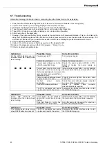
Indication
Possible Cause
Corrective Action
The “Alarm” and “Safety” LEDs
illuminate from time to time
without apparent reason
Optical head may be slightly
contaminated (fingerprints or
dust).
Remove power from the sensor and clean the
optical head (see section 6.4 “Advice on
maintenance”).
The EMI in the environment
exceeds standard specifications.
Install an electrical noise filter between the
power supply and sensor.
Power supply voltage may
fluctuate be from a source that
provides power to actuators.
Ensure the power supply is not the same
source used for actuators. Replace the power
source as required.
If the scanner is not mounted
directly onto the machine’s body,
the earth ground connection may
be poor or non-existent. A good
ground connection is crucial to
ensure EMI immunity.
Ensure a quality earth ground connection
exists via a dedicated wire on the power cable
or ground screw.
Electrical actuator switching,
especially when the coil of an
actuator is NOT protected against
the generation of electrical noise,
may cause false triggering (on
the SAFETY or ALARM output)
Install varistor protection to minimize electrical
noise interference.
Light sources or reflective
surfaces (like glass, metal foil
transparent plastic,…) located
around the scanner may cause
false triggering.
Remove or block out the light source or the
reflective surfaces. If not possible, change the
angle of the laser scanner to prevent sensing
these sources.
Rain, snow, fog, smoke and dust
may be detected as objects.
Protect the scanner from air pollution. Do not
use the scanner outdoors
If a second scanner is located
close to a scanner, the installed
sensor, mutual interference may
occur.
Remove the mutual interference caused by
the other FF-SE scanner (see section 4.4
Mounting);
If a light source like a
stroboscope is located close to
the installed sensor, light
interference may exist.
Remove the light source causing the
interference.
If the RS232 cable is still
connected to the sensor,
electrical noise interference may
be induced into the sensor.
Remove the RS232 cable from the scanner.
An object is detected
intermittently. The installation
environment may have changed
(the detected object could be the
floor).
Ensure that no object is detected by the FF-
SE. (consider the required 250 mm (9.8 in)
stand off distance from obtacles). Connect the
computer. Select the function “Monitor” in the
main menu. Modify the environment to its
original installation characteristics or modify
the protection zones.
Moving objects located close to
the limits of safety and alarm
zones may cause detection.
Check to see that no moving object is
detected by the FF-SE. Connect the
computer. Select the function “Monitor” in the
main menu. Remove the objects or redefine
the safety and alarm zones.
Summary of Contents for SYA14 Series
Page 2: ...2 107031 23 EN FR26 GLO 1199 Printed in France This page has been left intentionally blank ...
Page 6: ...6 107031 23 EN FR26 GLO 1199 Printed in France This page has been left intentionally blank ...
Page 26: ...26 107031 23 EN FR26 GLO 1199 Printed in France This page has been left intentionally blank ...
Page 62: ...62 107031 23 EN FR26 GLO 1199 Printed in France This page has been left intentionally blank ...
Page 70: ...70 107031 23 EN FR26 GLO 1199 Printed in France This page has been left intentionally blank ...
Page 76: ...76 107031 23 EN FR26 GLO 1199 Printed in France This page has been left intentionally blank ...
Page 78: ...78 107031 23 EN FR26 GLO 1199 Printed in France This page has been left intentionally blank ...
Page 79: ...107031 23 EN FR26 GLO 1199 Printed in France 79 8 CE Declaration of Conformity ...
Page 80: ...80 107031 23 EN FR26 GLO 1199 Printed in France This page has been left intentionally blank ...
Page 84: ......
Page 158: ......
Page 160: ......
Page 161: ...For application help call 1 800 537 6945 Honeywell MICRO SWITCH Sensing and Control 80 ...
Page 165: ...3 107022 14 EN FR26 GLO 0100 Printed in Germany This page has been left intentionally blank ...
Page 201: ...39 107022 14 EN FR26 GLO 0100 Printed in Germany This page has been left intentionally blank ...
Page 205: ...43 107022 14 EN FR26 GLO 0100 Printed in Germany This page has been left intentionally blank ...
Page 207: ...45 107022 14 EN FR26 GLO 0100 Printed in Germany This page has been left intentionally blank ...
Page 208: ...107022 14 EN FR26 GLO 0100 Printed in Germany 46 9 Declaration of Conformity ...
Page 219: ...11 107006 11 EN FR26 GLO 0300 Printed in Germany This page has been left intentionally blank ...
Page 229: ...21 107006 11 EN FR26 GLO 0300 Printed in Germany This page has been left intentionally blank ...
Page 257: ...49 107006 11 EN FR26 GLO 0300 Printed in Germany This page has been left intentionally blank ...
Page 260: ...107006 11 EN FR26 GLO 0300 Printed in Germany 52 9 3 Declaration of conformity ...
Page 340: ...Safety Perimeter Guarding Installation Manual FF SPS4 Series Safety Perimeter Guarding ...
Page 536: ...2 107004 15 EN FR26 ROW 0899 Printed in France This page has been left intentionally blank ...
Page 538: ...4 107004 15 EN FR26 ROW 0899 Printed in France This page has been left intentionally blank ...
Page 542: ...107004 15 EN FR26 ROW 0899 Printed in France 8 This page has been left intentionally blank ...
Page 620: ...86 107004 15 EN FR26 ROW 0899 Printed in France This page has been left intentionally blank ...
Page 624: ...90 107004 15 EN FR26 ROW 0899 Printed in France This page has been left intentionally blank ...
Page 626: ...92 107004 15 EN FR26 ROW 0899 Printed in France This page has been left intentionally blank ...
Page 627: ...107004 15 EN FR26 ROW 0899 Printed in France 93 8 CE Declaration of Conformity ...
Page 628: ...94 107004 15 EN FR26 ROW 0899 Printed in France This page has been left intentionally blank ...


