Serie 50FY
NÚMERO 3
PK 80391
Honeywell
•
MICRO SWITCH Sensing & Control
3
Paso 3 - Conecte los sensores al amplificador lógico de
la siguiente manera:
AVISO
•
No pueden solicitarse versiones antiguas de los
componentes (amplificador FYQLA-140R-1 y sensor
50FY40). No obstante, para propósitos de mantenimiento,
los componentes nuevos (amplificador FYQLA-140R-3 y
sensor 50FY41) pueden utilizarse en una instalación
antigua (véase la advertencia sobre la instalación).
•
Los accionadores de imán 52FY30 funcionarán con
sensores 50FY41, no obstante, la distancia de detección
aumentará.
a. Sensor 50FY41 (nuevo) con amplificador FYQLA1-140R-
3 (nuevo)
•
Conecte cada sensor (véase el Diagrama de cableado) al
amplificador lógico por medio de sus cuatro conectores de
la siguiente manera:
FYQLA1-140R-3 (nuevo)
50FY41 (nuevo)
R (positivo)
ROJO - positivo
B (normalmente abierto)
BLANCO - salida
Ne (negativo)
NEGRO - a tierra
Na (normalmente cerrado)
NARANJA - salida
•
Para asegurar los conductores de alimentación y del
sensor, ajuste los tornillos conectores con un par torsor de
0,56 Nm (5.0 pulg.-lb).
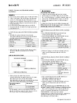
DIAGRAMA DE CABLEADO
NEGRO (A TIERRA)
ROJO (POSITIVO)
BLANCO (SALIDA)
NARANJA (SALIDA)
•
Si están conectados menos de seis sensores al
amplificador lógico, instale dos reóstatos de 22 K
Ω
a
través de cada conjunto terminal sin utilizar del
amplificador lógico de la siguiente manera:
Terminales del amplificador
lógico
Reóstato*
R - B
reóstato de 22 K
Ω
Ne -Na
reóstato de 22 K
Ω
*Los reóstatos son necesarios para el correcto
funcionamiento del amplificador lógico. Se suministran
diez reóstatos de 22 K
Ω
con cada sistema de la Serie
50FY.
ADVERTENCIA
INSTALACIÓN INADECUADA
•
Este producto está diseñado para cumplir con los
requerimientos técnicos de EN954 Categoría III y ANSI
B11.19-1990. Para asegurar el cumplimento con estos
requerimientos, los sensores 50FY41 DEBEN utilizarse
con el amplificador lógico FYQLA1-140R-3.
•
Siga estrictamente todas las instrucciones de instalación.
El incumplimiento de estas instrucciones podría
provocar la muerte o lesiones graves.
b. Sensor 50FY41 (nuevo) con amplificador FYQLA1-140R-
1 (antiguo)
•
Corte y retire el cable conductor NARANJA del sensor.
•
Conecte los cables conductores ROJO, BLANCO y
NEGRO del sensor a las terminales del amplificador
lógico de la siguiente manera:
FYQLA1-140R-1 (antiguo)
50FY41 (nuevo)
R (positivo)
ROJO - positivo
B (normalmente abierto)
BLANCO - salida
Ne (negativo)
NEGRO - a tierra
NARANJA ELIMINADO
•
Para asegurar los conductores de alimentación y del
sensor, ajuste los tornillos conectores con un par torsor de
0,56 Nm (5.0 pulg.-lb).
c. Sensor 50FY40 (antiguo) con amplificador FYQLA1-
140R-3 (nuevo)
•
Conecte los cables conductores ROJO, BLANCO y
NEGRO del sensor al amplificador lógico de la siguiente
manera:
FYQLA1-140R-3 (nuevo)
50FY40 (antiguo)
R (positivo)
ROJO - positivo
B (normalmente abierto)
BLANCO - salida
Ne (negativo)
NEGRO - a tierra
Na (normalmente cerrado)
SIN CONDUCTOR
NARANJA
•
Instale un reóstato de 22 K
Ω
entre las terminales NEGRA
y NARANJA del amplificador lógico.
•
Para asegurar los conductores de alimentación y del
sensor, ajuste los tornillos conectores con un par torsor de
0,56 Nm (5.0 pulg.-lb).
Instrucciones especiales para los sensores 50FY40
utilizados con el amplificador FYQLA1-140R-3
Si la puerta permanece abierta por más de un segundo y
la energía hacia el amplificador está CONECTADA (ON), el
LED INDICADOR DE ATENCIÓN destellará. Para regresar
a una condición verde, cierre la(s) puerta(s), DESCONECTE
(OFF) la energía del amplificador, y espere hasta que el LED
INDICADOR DE ATENCIÓN esté completamente
APAGADO (OFF), luego CONECTE (ON) la energía del
amplificador (energía en reposición).
Summary of Contents for SYA14 Series
Page 2: ...2 107031 23 EN FR26 GLO 1199 Printed in France This page has been left intentionally blank ...
Page 6: ...6 107031 23 EN FR26 GLO 1199 Printed in France This page has been left intentionally blank ...
Page 26: ...26 107031 23 EN FR26 GLO 1199 Printed in France This page has been left intentionally blank ...
Page 62: ...62 107031 23 EN FR26 GLO 1199 Printed in France This page has been left intentionally blank ...
Page 70: ...70 107031 23 EN FR26 GLO 1199 Printed in France This page has been left intentionally blank ...
Page 76: ...76 107031 23 EN FR26 GLO 1199 Printed in France This page has been left intentionally blank ...
Page 78: ...78 107031 23 EN FR26 GLO 1199 Printed in France This page has been left intentionally blank ...
Page 79: ...107031 23 EN FR26 GLO 1199 Printed in France 79 8 CE Declaration of Conformity ...
Page 80: ...80 107031 23 EN FR26 GLO 1199 Printed in France This page has been left intentionally blank ...
Page 84: ......
Page 158: ......
Page 160: ......
Page 161: ...For application help call 1 800 537 6945 Honeywell MICRO SWITCH Sensing and Control 80 ...
Page 165: ...3 107022 14 EN FR26 GLO 0100 Printed in Germany This page has been left intentionally blank ...
Page 201: ...39 107022 14 EN FR26 GLO 0100 Printed in Germany This page has been left intentionally blank ...
Page 205: ...43 107022 14 EN FR26 GLO 0100 Printed in Germany This page has been left intentionally blank ...
Page 207: ...45 107022 14 EN FR26 GLO 0100 Printed in Germany This page has been left intentionally blank ...
Page 208: ...107022 14 EN FR26 GLO 0100 Printed in Germany 46 9 Declaration of Conformity ...
Page 219: ...11 107006 11 EN FR26 GLO 0300 Printed in Germany This page has been left intentionally blank ...
Page 229: ...21 107006 11 EN FR26 GLO 0300 Printed in Germany This page has been left intentionally blank ...
Page 257: ...49 107006 11 EN FR26 GLO 0300 Printed in Germany This page has been left intentionally blank ...
Page 260: ...107006 11 EN FR26 GLO 0300 Printed in Germany 52 9 3 Declaration of conformity ...
Page 340: ...Safety Perimeter Guarding Installation Manual FF SPS4 Series Safety Perimeter Guarding ...
Page 536: ...2 107004 15 EN FR26 ROW 0899 Printed in France This page has been left intentionally blank ...
Page 538: ...4 107004 15 EN FR26 ROW 0899 Printed in France This page has been left intentionally blank ...
Page 542: ...107004 15 EN FR26 ROW 0899 Printed in France 8 This page has been left intentionally blank ...
Page 620: ...86 107004 15 EN FR26 ROW 0899 Printed in France This page has been left intentionally blank ...
Page 624: ...90 107004 15 EN FR26 ROW 0899 Printed in France This page has been left intentionally blank ...
Page 626: ...92 107004 15 EN FR26 ROW 0899 Printed in France This page has been left intentionally blank ...
Page 627: ...107004 15 EN FR26 ROW 0899 Printed in France 93 8 CE Declaration of Conformity ...
Page 628: ...94 107004 15 EN FR26 ROW 0899 Printed in France This page has been left intentionally blank ...


