FF-SB Installation Manual
For application help: call 1-800-537-6945
Honeywell
•
MICRO SWITCH Sensing and Control 71
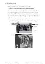
9. Place replacement module in position and plug the flat cable connector into the socket.
Retain it with two moving parts.
10. Position all the optical modules on the plastic support and ensure they are correctly
aligned. Using a Philip’s screwdriver, install and tighten all screws.
11. Aligning the slots in the plastic support with those on the housing, gently push the optical
controller module into the housing.
12. Aligning the straight ends of the retaining rods with the slot next to the lens holders, slide
the rods in (see figure 4-11) and turn them to secure into position. The retaining rod ends
must be vertical to close the unit.
13. Perform the Power Supply Module Replacement procedure.
Jumper
Summary of Contents for SYA14 Series
Page 2: ...2 107031 23 EN FR26 GLO 1199 Printed in France This page has been left intentionally blank ...
Page 6: ...6 107031 23 EN FR26 GLO 1199 Printed in France This page has been left intentionally blank ...
Page 26: ...26 107031 23 EN FR26 GLO 1199 Printed in France This page has been left intentionally blank ...
Page 62: ...62 107031 23 EN FR26 GLO 1199 Printed in France This page has been left intentionally blank ...
Page 70: ...70 107031 23 EN FR26 GLO 1199 Printed in France This page has been left intentionally blank ...
Page 76: ...76 107031 23 EN FR26 GLO 1199 Printed in France This page has been left intentionally blank ...
Page 78: ...78 107031 23 EN FR26 GLO 1199 Printed in France This page has been left intentionally blank ...
Page 79: ...107031 23 EN FR26 GLO 1199 Printed in France 79 8 CE Declaration of Conformity ...
Page 80: ...80 107031 23 EN FR26 GLO 1199 Printed in France This page has been left intentionally blank ...
Page 84: ......
Page 158: ......
Page 160: ......
Page 161: ...For application help call 1 800 537 6945 Honeywell MICRO SWITCH Sensing and Control 80 ...
Page 165: ...3 107022 14 EN FR26 GLO 0100 Printed in Germany This page has been left intentionally blank ...
Page 201: ...39 107022 14 EN FR26 GLO 0100 Printed in Germany This page has been left intentionally blank ...
Page 205: ...43 107022 14 EN FR26 GLO 0100 Printed in Germany This page has been left intentionally blank ...
Page 207: ...45 107022 14 EN FR26 GLO 0100 Printed in Germany This page has been left intentionally blank ...
Page 208: ...107022 14 EN FR26 GLO 0100 Printed in Germany 46 9 Declaration of Conformity ...
Page 219: ...11 107006 11 EN FR26 GLO 0300 Printed in Germany This page has been left intentionally blank ...
Page 229: ...21 107006 11 EN FR26 GLO 0300 Printed in Germany This page has been left intentionally blank ...
Page 257: ...49 107006 11 EN FR26 GLO 0300 Printed in Germany This page has been left intentionally blank ...
Page 260: ...107006 11 EN FR26 GLO 0300 Printed in Germany 52 9 3 Declaration of conformity ...
Page 340: ...Safety Perimeter Guarding Installation Manual FF SPS4 Series Safety Perimeter Guarding ...
Page 536: ...2 107004 15 EN FR26 ROW 0899 Printed in France This page has been left intentionally blank ...
Page 538: ...4 107004 15 EN FR26 ROW 0899 Printed in France This page has been left intentionally blank ...
Page 542: ...107004 15 EN FR26 ROW 0899 Printed in France 8 This page has been left intentionally blank ...
Page 620: ...86 107004 15 EN FR26 ROW 0899 Printed in France This page has been left intentionally blank ...
Page 624: ...90 107004 15 EN FR26 ROW 0899 Printed in France This page has been left intentionally blank ...
Page 626: ...92 107004 15 EN FR26 ROW 0899 Printed in France This page has been left intentionally blank ...
Page 627: ...107004 15 EN FR26 ROW 0899 Printed in France 93 8 CE Declaration of Conformity ...
Page 628: ...94 107004 15 EN FR26 ROW 0899 Printed in France This page has been left intentionally blank ...


