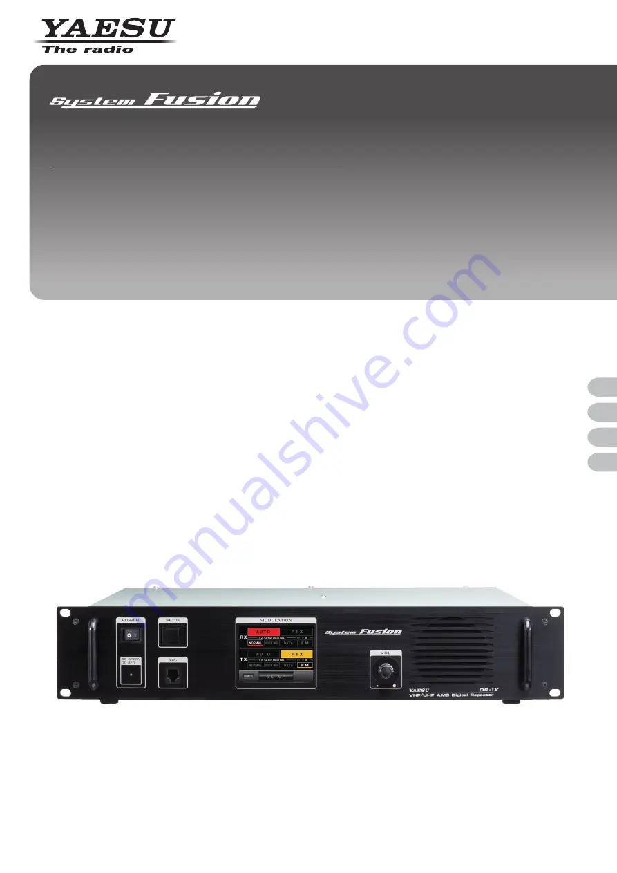
background image

Before Using

Installation and Connection

Operations

Appendix

144/430MHz 50W

VHF/UHF AMS DIGITAL REPEATER

C4FM FDMA/FM

DR-1X / DR-1XE

Operating Manual

Summary of Contents for DR-1X

Page 1: ...Before Using Installation and Connection Operations Appendix 144 430MHz 50W VHF UHF AMS DIGITAL REPEATER C4FM FDMA FM DR 1X DR 1XE Operating Manual...

Page 2: ...th to wipe away dust and dirt from the touch panel When the touch panel is really dirty wet a soft cloth and wring it out thoroughly before using it to wipe the touch panel When wiping the touch panel...

Page 3: ...the squelch level 22 Adjusting the transmit power 23 Setting the TX Inhibit 24 Remote Operation 25 Turning remote operation ON OFF 25 Control from external controller 26 Base Station Operation 27 Tra...

Page 4: ...OFF the power supply If not fire electric shock and equipment failure this may result Do not touch any liquid leaking from the liquid display with your bare hands There is a risk of chemical burns oc...

Page 5: ...n top of the power cord and connection cables This may damage the power cord and connection cables resulting in fire and electric shock Do not transmit near the television and radio This may result in...

Page 6: ...Fuse T9026115 1 Spare Fuse 15 A Q0000075 1 5 A Q0000143 1 1 Case Legs S4000052 4 PC Connection Cable SCU 20 T9101621 1 Operating Manual this manual 1 Warranty Certificate 1 1 For DR 1X only Options D...

Page 7: ...indicator illuminates in red the power supply is backed up through the BACKUP terminals 13 8 V DC SETUP button Press to switch the display on and off MIC jack Insert the plug of the optional microphon...

Page 8: ...rement is 50 ohms FUSE 15A jack A 15 A fuse for the DC power supply through the BACKUP terminals is attached BACKUP terminals Connect to the 13 8 V DC power supply FUSE 5A jack DR 1X only A 5 A fuse f...

Page 9: ...e and yellow during the FIX mode NORMAL Indicates operation is in the simultaneous voice and data communication mode digital VOICE WIDE Indicates operation is in the high rate voice communication mode...

Page 10: ...evel F Touch here to display the setup menu Direction display area UP LINK is displayed on the RX band DOWN LINK is displayed on the TX band Status display area A green bar is displayed during receive...

Page 11: ...ipation is not obstructed The heat sink becomes hot when transmitting for long periods of time Do not place any objects on top of the repeater Note that there is a risk that hum and noise may be intro...

Page 12: ...of 50 Keep the coaxial cable routing length as short as possible Use lightening and voltage surge protection devises Antenna consideration Repeater operation without a duplexer requires that two anten...

Page 13: ...onto the jacks Note The figure above shows the rear panel of the DR 1X 2 To use a duplexer prepared by yourself plug in the terminal of the coaxial cables from the TX ANT and RX ANT terminals into the...

Page 14: ...for a long time the battery may be completely discharged When the power is restored the DC startup current may blow the protection fuse So the protection fuse in charge circuit should be checked after...

Page 15: ...cord to the DC IN jack at the rear of the repeater 2 Connect the red wire of the provided DC power cord to the positive terminal of the external power source and the black wire to the negative termin...

Page 16: ...to a personal computer as a COM port Use the ACC jack at the back of the repeater to connect with the personal computer The pin assignments of the ACC jack are as follows PKD packet data input GND PSK...

Page 17: ...control This pin is sub audible tone input and has a flat response characteristic repeater deviation is constant for a given signal level over the frequency range of 5 250 Hz Injecting a too high sig...

Page 18: ...riminator output 9 AF OUT Digital Demodulated digital audio output Analog Analog audio output Caution Even when using the DR 1X DR 1XE with an external controller the COR analog and digital IDs TOT DS...

Page 19: ...uch F in the setup mode screen The setup menu will appear 2 Touch ID SET The character input screen will appear 5 6 7 2 8 G T Z Z Z 2 72 0 0 19 0 8 53 6Z 294 5 6 00170 1 4 16 616 53 1 OKP 5 0 0 53 4 1...

Page 20: ...on Tip The display can be set to turn off automatically after a period of time with no operation See Setting the display turn on time Page 37 for details Adjusting the volume 1 Turn the VOL knob The m...

Page 21: ...transmitted in the previously selected communication mode Tip In the factory default the RX band is set to the AUTO mode and the TX band to the FIX mode 1 Touch AUTO to activate the AMS automatic mode...

Page 22: ...andwidth High quality voice communication is possible Data FR mode High speed data communication mode DATA DW High speed data communication mode using the entire 12 5 kHz bandwidth for data communicat...

Page 23: ...previous screen 5 6 7 2 8 G T Z Z Z 2 72 0 0 19 0 8 53 Adjusting the transmit power The transmit power can be reduced to save on power consumption 1 Touch SETUP The setup mode screen will appear 2 Tou...

Page 24: ...19 0 8 53 6Z 294 5 6 00170 1 4 16 616 53 1 OKP 5 0 0 53 4 1 6 1 4 Select TX INHIBIT 4 16 6 0 6 6 4 1 1 1 4 16 6 0 6 52 6 4 5 Touch TX INHIBIT The set value will change between OFF and ON each time it...

Page 25: ...according to the control instructions received from the external controller the instructions are received through Pin 11 to Pin 14 of the CONTROL I O connector When the remote operation is OFF the re...

Page 26: ...dulation input 600 ohm 1 5 V peak to peak Valid during external PTT control Caution It is impossible to input analog modulation signals and convert them to digital signals on DR 1X DR 1XE Tip AF IN is...

Page 27: ...ing from 1200 bps If the repeater is expected to transmit digital modulation signals while in base station operation set the packet speed to 9600 bps before starting base station operation as below 1...

Page 28: ...tup menu will appear 5 6 7 2 8 G T Z Z Z 2 72 0 0 19 0 8 53 6Z 294 3 Touch the menu item The menu list will appear 5 6 7 2 8 G T Z Z Z 2 72 0 0 19 0 8 53 6Z 294 5 6 00170 1 4 16 616 53 1 OKP 5 0 0 53...

Page 29: ...e screen Tips Each time is touched the cursor will move to the left and erase one character Touch the DOWN LINK or UP LINK area to change the frequency setting between TX or RX When the last digit is...

Page 30: ...r The set value will change each time it is touched Tips Tone frequencies between 67 0 Hz and 254 1 Hz can be selected Factory default 100 0 Hz 5 6 7 2 8 G T Z Z Z 2 72 0 0 19 0 8 53 6Z 294 1 610 53 4...

Page 31: ...ppear 2 Touch SQL in the setup menu The menu list will appear 5 6 7 2 8 G T Z Z Z 2 72 0 0 19 0 8 53 6Z 294 53 4 1 6 1 5 6 00170 1 4 16 616 53 1 OKP 5 0 0 3 Select RX SQL to set the tone signal type d...

Page 32: ...ted Factory default OFF 5 6 7 2 8 G T Z Z Z 2 72 0 0 19 0 8 53 6Z 294 1 53 1 4 Touch BACK The setting is determined and the display will return to the setup menu The set value will be displayed below...

Page 33: ...the radio a screen will be displayed requesting the repeater ID entered 3 9 4 6 7 1 2 5 8 0 5RCEG 06 CRU 5 6 2 Setting the ID announcement Setting the way to announce 1 Touch F in the setup mode scree...

Page 34: ...nd touch ANNOUNCE LEVEL The set value will change in the following sequence each time it is touched HIGH MID LOW Tip Factory default MID 00170 9 YF OKP 00170 1 00170 8 9 52 5 Touch BACK The setting is...

Page 35: ...uncement time interval 1 Touch F in the setup mode screen The setup menu will appear 2 Touch ID ANNOUNCE The menu list will appear 5 6 7 2 8 G T Z Z Z 2 72 0 0 19 0 8 53 6Z 294 5 6 00170 1 4 16 616 53...

Page 36: ...n 2min 2 5min 3min 4min 5min 10min Tip Factory default 3min 5 6 7 2 8 G T Z Z Z 2 72 0 0 19 0 8 53 6Z 294 1 616 OKP 4 Touch BACK The setting is determined and the display will return to the setup menu...

Page 37: ...hed CONTINUE 1min 5min 10min 30min Tip Factory default CONTINUE 4 16 6 0 6 6 4 1 1 OKP 4 16 6 0 6 52 6 4 5 Touch BACK The setting is determined and the display will return to the menu list Setting the...

Page 38: ...e setup mode screen The setup menu will appear 5 Touch F The reset confirmation screen will appear 5 6 7 2 8 G T Z Z Z 2 72 0 0 19 0 8 53 6Z 294 5 6 00170 1 4 16 616 53 1 OKP 5 0 0 53 4 1 6 1 6 Touch...

Page 39: ...DR 1X Figure 1 4 Referring to Figure 2 remove the 4 screws from the top cover of the RX Unit then remove the top cover Figure 2 5 Refer to Figure 3 for the mounting location for the FVS 2 Figure 3 6...

Page 40: ...e stains Caution Never use washing detergents or organic solvents thinner benzene etc These may result in the paint peeling off or the cover being damaged Replacing the fuse When the fuses attached at...

Page 41: ...ere may be some internal heterodynes due to the high frequency of the internal oscillator However this is not a malfunction refer to the calculation formula below n is any integer Depending on the com...

Page 42: ...ept any interference received including interference that may cause undesired operation Specifications General Frequency range 144 to 146 MHz 430 to 440 MHz 144 to 148 MHz 430 to 450 MHz Channel steps...

Page 43: ...b The technical documentation as required by the Conformity Assessment procedures is kept at the following address Company Yaesu UK Ltd Address Unit 12 Sun Valley Business Park Winnall Close Winchest...

Page 44: ...U USA 6125 Phyllis Drive Cypress CA 90630 U S A YAESU UK Unit 12 Sun Valley Business Park Winnall Close Winchester Hampshire SO23 0LB U K 1406J 0S Printed in Japan Copyright 2014 YAESU MUSEN CO LTD Al...

Reviews: