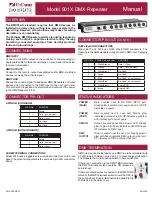
Model 901X DMX Repeater
Manual
901X-300-REV1
05/24/19
5-PIN XLR (STANDARD)
3-PIN XLR (NON-STANDARD)
SCREW TERMINAL CONNECTIONS
Model 9015 uses pluggable screw terminal connectors on the rear
panel. The pinout arrangement is the same as 5-pin XLR connectors
above.
The DMX512-A standard requires that DMX devices be
installed in a daisy chain, with no tees, wyes or stars in the
data wiring. However, site conditions may make star wiring
desirable or even mandatory.
The Pathway DMX Repeater permits star-wiring layouts by
making each output a separate electrical entity, thereby
protecting connected equipment from harmful electrical
faults and ground loops.
DMX INPUT
Connect to the DMX output of the controller or console using an
appropriate cable for the connector type on your model. (See below
for pinout information).
DMX OUTPUTS
Connect to the remote output receptacles and/or DMX-controlled
devices receiving the console signal.
DMX THRU
Passes the console signal to additional DMX Repeaters or similar
devices when connected to the DMX input on the next unit in line.
This connection is passive and unisolated and will work if the power
to the DMX Repeater is lost.
OVERVIEW
CONNECTIONS
CONNECTOR PIN OUT
STATUS INDICATORS
DMX TERMINATION
CONNECTOR PIN OUT
(CONT’D)
RJ45 etherCON CONNECTORS
Model 9017 and 9018 use RJ45 etherCON® connectors. The
following is the ANSI standard wiring pin out for DMX-over-Category
wire.
DMX rules require the last device on a DMX line to be terminated with
a 120Ω resistor between pins 2 and 3 to prevent signal reflection.
The Repeater has a termination switch to accomplish this.
If there is no connection to the DMX THRU terminals,
the DMX Terminate switch should be ON (pressed in
and latched).
If there are other devices connected to the DMX THRU
terminal, the DMX Terminate switch should be OFF (in
the out position). Ensure termination is applied to the
final device in the daisy-chain.
POWER
(MAIN)
Blue.
Located next to the DMX INPUT port.
Steady glow indicates main power input is OK. Off
indicates no power.
POWER
(PORT)
Blue.
Located next to each port. Steady glow
indicates port power is OK. Off indicates a problem
with internal port power supply.
DMX IN
Amber
. Located above Main Power LED. Steady
glow or glow with flicker indicates valid DMX input.
Off indicates no DMX input.
DMX
OUTPUT
Green
. Located next to each port. Steady glow or
glow with flicker indicates DMX output by that port.
Off indicates no DMX output at that port.
XLR PIN #
PURPOSE
1
Shield
2
Data - (complement)
3
Data + (true)
4
Not Used
5
Not Used
XLR PIN #
PURPOSE
1
Shield
2
Data - (complement)
3
Data + (true)
XLR PIN # CAT5/6 Pin # and Color
PURPOSE
3
1 - White/Orange
Data 1 + (true)
2
2 - Orange
Data 1 - (complement)
5
3 - White/Green
Not Used
4
6 - Green
Not Used
-
4 - Blue
Not Used - do not connect
-
5 - White/Blue
Not Used - do not connect
1
7 - White/Brown
Shield/COM
1
8 - Brown
Shield/COM

