Actual signals and parameters
178
21.04
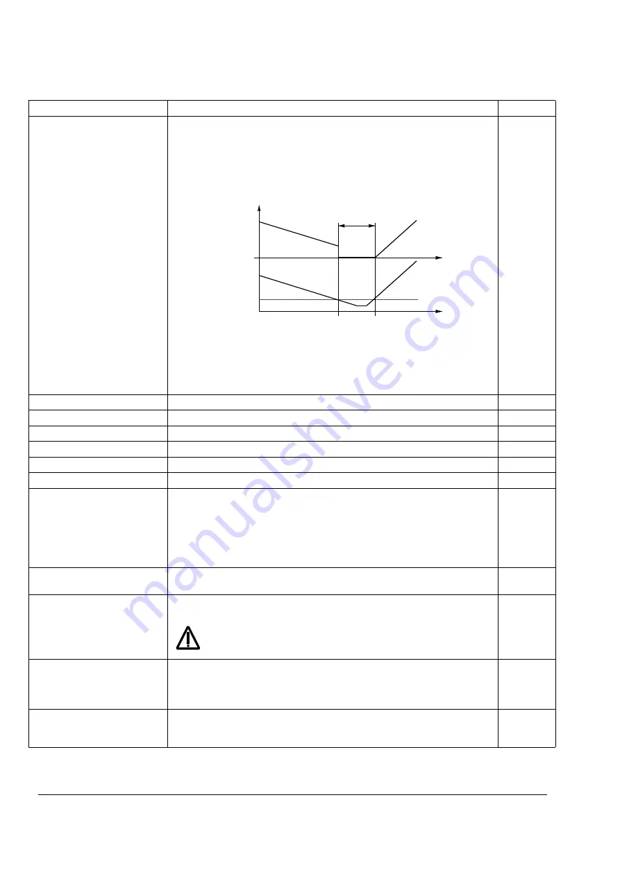
DC HOLD
Activates/deactivates the DC hold function. DC hold is not possible if
parameter
= SCALAR.
When both the reference and the speed drop below the value of parameter
, the drive will stop generating sinusoidal current and start to inject DC
into the motor. The current is set with parameter
speed exceeds parameter
, normal drive operation continues.
Note:
DC hold has no effect if the start signal is switched off.
Note:
Injecting DC current into the motor causes the motor to heat up. In
applications where long DC hold times are required, externally ventilated
motors should be used. If the DC hold period is long, the DC hold cannot
prevent the motor shaft from rotating if a constant load is applied to the motor.
NO
Inactive
0
YES
Active
65535
21.05
DC HOLD SPEED
Defines the DC hold speed. See parameter
.
0 … 3000 rpm
Speed in rpm
0 … 3000
21.06
DC HOLD CURR
Defines the DC hold current. See parameter
.
0 … 100%
Current in percent of the motor nominal current
0 … 100
21.07
RUN ENABLE FUNC
Selects the stop mode applied when Run Enable signal is switched off. Run
Enable signal is put into use with parameter
.
Note:
In the Master/Follower mode, the settings must be the same in both the
Master and the Follower drives.
Note:
The setting overrides the normal stop mode setting (parameter
when Run Enable signal is switched off.
RAMP STOP
The application program stops the drive along the deceleration ramp defined in
group
1
COAST STOP
The application program stops the drive by cutting off the motor power supply
(the inverter IGBTs are blocked). The motor rotates freely to zero speed.
WARNING!
If the brake control function is on, the application program
uses ramp stop in spite of the selection COAST STOP (see parameter
group
).
2
OFF2 STOP
The application program stops the drive by cutting off the motor power supply
(the inverter IGBTs are blocked). The motor rotates freely to zero speed. The
drive will restart only when the Run Enable signal is on and the start signal is
switched on (the program receives the rising edge of the start signal).
3
OFF3 STOP
The application program stops the drive along the ramp defined with parameter
. The drive will restart only when the Run Enable is on and the start signal
is switched on (the program receives the rising edge of the start signal).
4
Index
Name/Selection
Description
FbEq
DC HOLD SPEED
t
t
SPEED
motor
Ref.
DC hold
Summary of Contents for ACS 800 Series
Page 1: ...ACS800 Firmware Manual Crane Control Program N697 ...
Page 4: ......
Page 26: ...Start up and control through the I O interface 26 ...
Page 36: ...Quick start up guide 36 ...
Page 52: ...Control panel 52 ...
Page 105: ...Program features 105 Figure Control diagram for Shaft synchronisation executed in 20 ms ...
Page 128: ...Program features 128 ...
Page 150: ...Application macros control location EXT1 EXT2 150 ...
Page 228: ...Actual signals and parameters 228 ...
Page 299: ...Adaptive Programming examples for crane control 299 ...
Page 305: ...Adaptive Programming examples for crane control 305 ...
Page 318: ...Analogue Extension Module 318 ...
Page 332: ...Additional data actual signals and parameters 332 ...
Page 334: ...DriveWindow 334 ...
Page 335: ...Control block diagrams 335 Control block diagrams ...
Page 336: ...Control block diagrams 336 ...
Page 337: ...Control block diagrams 337 ...
Page 338: ...Control block diagrams 338 ...
Page 340: ...www abb com drives www abb com drivespartners Contact us 3AFE68775230 Rev E EN 2012 09 25 ...


