Actual signals and parameters
189
THERMISTOR
Motor thermal protection is activated through digital input DI6. A motor
thermistor, or a break contact of a thermistor relay, must be connected to digital
input DI6. The drive reads the DI6 states as follows:
WARNING!
According to IEC 664, the connection of the motor
thermistor to the digital input requires double or reinforced insulation
between motor live parts and the thermistor. Reinforced insulation
entails a clearance and creeping distance of 8 mm (400 / 500 V AC
equipment). If the thermistor assembly does not fulfil the requirement, the other
I/O terminals of the drive must be protected against contact, or a thermistor
relay must be used to isolate the thermistor from the digital input.
WARNING!
Digital input DI6 may be selected for another use. Change
these settings before selecting THERMISTOR. In other words, ensure
that digital input DI6 is not selected with any other parameter.
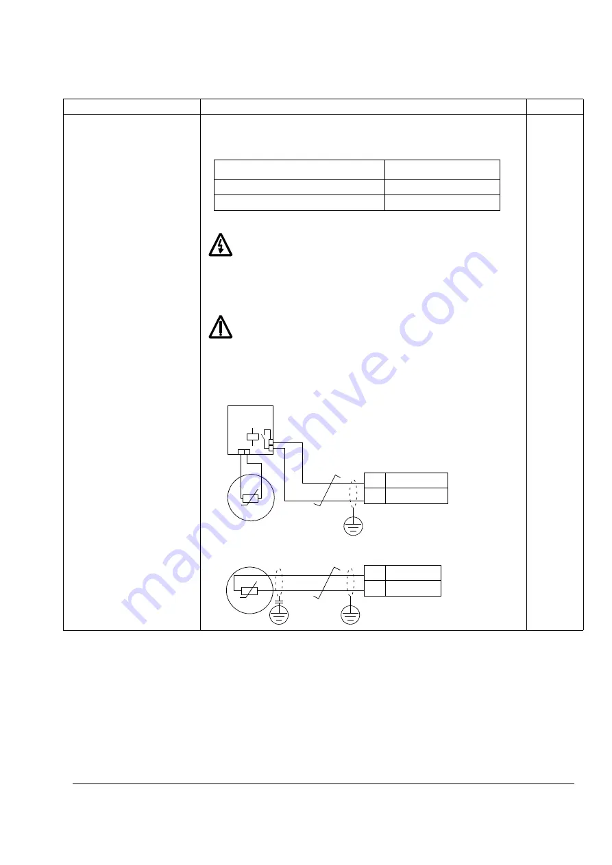
The figure below shows the alternative thermistor connections. At the motor
end the cable shield should be earthed through a 10 nF capacitor. If this is not
possible, the shield is to be left unconnected.
3
Index
Name/Selection
Description
FbEq
DI6 Status (Thermistor resistance)
Temperature
1 (0 … 1.5 kohm)
Normal
0 (4 kohm or higher)
Overtemperature
Motor
T
10 nF
Motor
T
Thermistor
relay
RMIO board, X22
6
DI6
7
+24 V DC
Alternative 1
Alternative 2
RMIO board, X22
6
DI6
7
+24 V DC
Summary of Contents for ACS 800 Series
Page 1: ...ACS800 Firmware Manual Crane Control Program N697 ...
Page 4: ......
Page 26: ...Start up and control through the I O interface 26 ...
Page 36: ...Quick start up guide 36 ...
Page 52: ...Control panel 52 ...
Page 105: ...Program features 105 Figure Control diagram for Shaft synchronisation executed in 20 ms ...
Page 128: ...Program features 128 ...
Page 150: ...Application macros control location EXT1 EXT2 150 ...
Page 228: ...Actual signals and parameters 228 ...
Page 299: ...Adaptive Programming examples for crane control 299 ...
Page 305: ...Adaptive Programming examples for crane control 305 ...
Page 318: ...Analogue Extension Module 318 ...
Page 332: ...Additional data actual signals and parameters 332 ...
Page 334: ...DriveWindow 334 ...
Page 335: ...Control block diagrams 335 Control block diagrams ...
Page 336: ...Control block diagrams 336 ...
Page 337: ...Control block diagrams 337 ...
Page 338: ...Control block diagrams 338 ...
Page 340: ...www abb com drives www abb com drivespartners Contact us 3AFE68775230 Rev E EN 2012 09 25 ...


