February 2013
2-531
ColorQube® 9303 Family
OF 3
Status Indicator RAPs
OF 3 Unresponsive Machine RAP
Use the following procedure if the machine fails to reach an operational state when switched
on. The UI screen display’s: blank, energy saver, splash only, progress and Xerox, or repeat-
edly cycles back to the install wizard screen each time the machine is switched on.
Initial Actions
WARNING
Ensure that the electricity to the machine is switched off while performing tasks that do
not need electricity. Refer to
GP 14
. Disconnect the power cord. Electricity can cause
death or injury. Moving parts can cause injury.
•
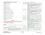
Check the SBC PWB 7-Segment LED display unit,
Figure 3
and the IME POST LED’s for
a POST error code,
OF 16
.
•
If the problem occurs while entering or exiting sleep mode, go to
OF 7
Sleep Mode RAP.
•
Open the image processing module,
PL 3.11
.
–
Reseat the system memory PWB,
PL 3.11 Item 4
.
–
Reseat the EPC memory PWB,
PL 3.11 Item 21
.
–
Check the battery on the NVM module PWB is located correctly and in good condi-
tion,
GP 45
.
–
Reseat the NVM module PWB,
PL 3.11 Item 17
.
–
Reseat the connectors on the single board controller PWB,
PL 3.11 Item 13
.
•
Check with the customer that their power supply is good. If necessary, connect the
machine to a known good AC supply. If the machine operates correctly at the new supply,
inform the customer that the original supply must be at fault.
•
Check that the SIM card is inserted correctly in the back of the machine. Refer to
GP 19
.
•
Disconnect the output device then temporarily install a finisher bypass connector,
PL
26.10 Item 7
.
•
If the UI screen displays the energy star green screen and the SBC PWB 7-Segment LED
display unit,
Figure 3
cycles through a sequence of 0 then alternating between 6 and U,
there is a hard drive fault. Ensure that the connectors on the hard drive are securely con-
nected. Ensure that PJ222 on the single board controller is securely connected.
Procedure
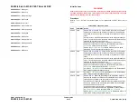
Switch on the machine,
GP 14
. Observe the power light button on the UI. The power button
flashes.
Y
N
Remove the rear cover,
PL 81.10 Item 1
. Observe the green LED on the power supply
unit,
Figure 1
. The green LED on the power supply unit is lit.
Y
N
Disconnect PJDC4 on the
Power Supply Unit.
Toggle the power switch. The green
LED is lit.
Y
N
Connect PJDC4. Disconnect PJDC3 on the
Power Supply Unit.
Toggle the
power switch. The green LED is lit.
Y
N
Connect PJDC3 and disconnect PJDC1. Toggle the power switch. The
green LED is lit.
Y
N
Go to
01A
AC Power Distribution RAP and perform the Main Power
Rocker Switch check. The switch is good
Y
N
Install a new main power rocker switch,
PL 1.15 Item 3
.
Install a new power supply unit,
PL 1.15 Item 2
.
The +3.3V ESTAR has a short circuit. Check for short circuits to chassis at
PJDC1 pins 14,15 and 16 refer to
WD 1.4
. Go to
01B
+3.3V ESTAR Distri-
bution RAP. Check the supply to the IME controller PWB,
PL 92.10 Item 1
.
There is a short or an over load in the marking unit on 3.3V ESTAR. Disconnect
all PJ’s from the
Media Path Driver PWB
and the
Drum Driver PWB
until the
short is found. If necessary refer to the following RAPs:
•
01B
+3.3V ESTAR Distribution RAP, refer to Drum driver PWB and Media
path driver PWB checkouts.
There is a short or an overload on the +17V or +3.3V supplies from the
Power Distri-
bution PWB
or the power distribution PWB is faulty. Disconnect all PJ’s until the fault
is found. If necessary refer to the following RAPs:
•
01G
+17V Distribution RAP.
•
01C
+3.3V Distribution RAP.
Go to the
01B
3.3V ESTAR Distribution RAP.
Remove the rear cover,
PL 81.10 Item 1
. Check the LED’s on the power supply unit,
Figure 1
.
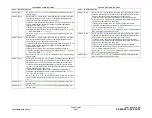
•
Orange LED ind24V, +/-12V and +5V are good.
•
Green LED ind3.3V ESTAR and +17V are good.
•
Red LED ind/-50V are good.
All LED’s are lit
Y
N
Go to the relevant voltage distribution RAP:
•
01B
+3.3V ESTAR Distribution RAP.
•
01D
+5V Distribution RAP.
•
01E
+12V Distribution RAP.
•
01F
-12V Distribution RAP.
•
01G
+17V Distribution RAP
•
01H
+24V Distribution RAP.
•
01J
+50V Distribution RAP.
•
01K
-50V Distribution RAP.
•
01L
0V Distribution RAP.
•
Refer to
01-540-00, 01-544-00
RAP and
01-542-00, 01-546-00
RAP.
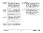
The green ‘Xerox’ screen is displayed.
Y
N
Go to
OF 2
UI Touch Screen Failure RAP. The UI is good
A
A
B
B
C
C
D
D
E
Summary of Contents for ColorQube 9303 Series
Page 1: ...Xerox ColorQube 9303 Family Service Manual 708P90290 February 2013...
Page 4: ...February 2013 ii ColorQube 9303 Family Introduction...
Page 18: ...February 2013 1 2 ColorQube 9303 Family Service Call Procedures...
Page 92: ...February 2013 2 68 ColorQube 9303 Family 05F Status Indicator RAPs...
Page 104: ...February 2013 2 80 ColorQube 9303 Family 12 701 00 65 Status Indicator RAPs...
Page 200: ...February 2013 2 176 ColorQube 9303 Family 12N 171 Status Indicator RAPs...
Page 292: ...February 2013 2 268 ColorQube 9303 Family 16D Status Indicator RAPs...
Page 320: ...February 2013 2 296 ColorQube 9303 Family 42 504 00 42 505 00 Status Indicator RAPs...
Page 500: ...February 2013 2 476 ColorQube 9303 Family 94B Status Indicator RAPs...
Page 648: ...February 2013 3 2 ColorQube 9303 Family Image Quality...
Page 653: ...February 2013 3 7 ColorQube 9303 Family IQ 1 Image Quality Figure 1 IQ defects 1...
Page 654: ...February 2013 3 8 ColorQube 9303 Family IQ 1 Image Quality Figure 2 IQ defects 2...
Page 655: ...February 2013 3 9 ColorQube 9303 Family IQ 1 Image Quality Figure 3 IQ defects 3...
Page 656: ...February 2013 3 10 ColorQube 9303 Family IQ 1 Image Quality Figure 4 IQ defects 4...
Page 657: ...February 2013 3 11 ColorQube 9303 Family IQ 1 Image Quality Figure 5 IQ defects 5...
Page 658: ...February 2013 3 12 ColorQube 9303 Family IQ 1 Image Quality Figure 6 IQ defects 6...
Page 660: ...February 2013 3 14 ColorQube 9303 Family IQ 1 Image Quality Figure 9 IQ defects 9...
Page 661: ...February 2013 3 15 ColorQube 9303 Family IQ 1 Image Quality Figure 10 IQ defects 10...
Page 662: ...February 2013 3 16 ColorQube 9303 Family IQ 1 Image Quality Figure 11 IQ defects 11...
Page 663: ...February 2013 3 17 ColorQube 9303 Family IQ 1 Image Quality Figure 12 IQ defects 12...
Page 664: ...February 2013 3 18 ColorQube 9303 Family IQ 1 Image Quality Figure 13 IQ defects 13...
Page 728: ...February 2013 3 82 ColorQube 9303 Family IQ 29 IQ 30 Image Quality...
Page 736: ...February 2013 3 90 ColorQube 9303 Family TP 15 Image Quality Figure 2 Media path test pages...
Page 758: ...February 2013 3 112 ColorQube 9303 Family IQS 7 IQS 8 Image Quality...
Page 778: ...February 2013 4 20 ColorQube 9303 Family REP 1 9 Repairs Adjustments...
Page 794: ...February 2013 4 36 ColorQube 9303 Family REP 3 10 Repairs Adjustments...
Page 1144: ...February 2013 4 386 ColorQube 9303 Family REP 94 1 Repairs Adjustments...
Page 1176: ...February 2013 4 418 ColorQube 9303 Family ADJ 62 3 ADJ 62 4 Repairs Adjustments...
Page 1182: ...February 2013 4 424 ColorQube 9303 Family ADJ 75 3 Repairs Adjustments...
Page 1184: ...February 2013 4 426 ColorQube 9303 Family ADJ 82 1 Repairs Adjustments...
Page 1186: ...February 2013 4 428 ColorQube 9303 Family ADJ 91 1 Repairs Adjustments...
Page 1552: ...February 2013 6 260 ColorQube 9303 Family dC140 General Procedures Information...
Page 1576: ...February 2013 6 284 ColorQube 9303 Family dC640 General Procedures Information...
Page 1578: ...February 2013 6 286 ColorQube 9303 Family dC708 dC715 General Procedures Information...
Page 1600: ...February 2013 7 2 ColorQube 9303 Family Wiring Data...
Page 1696: ...February 2013 8 2 ColorQube 9303 Family Principles of Operation...
Page 1808: ...February 2013 8 114 ColorQube 9303 Family Principles of Operation...
Page 1809: ...XEROX EUROPE...
Page 1810: ...XEROX EUROPE...
Page 1811: ...XEROX EUROPE...
Page 1812: ...XEROX EUROPE...


