February 2013
8-85
ColorQube® 9303 Family
Principles of Operation
Entry Sensor
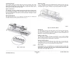
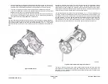
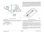
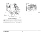
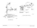
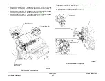
Entry Sensor Q12-077 is located in the LCSS entrance paper path. In addition to supplying the
LCSS PWB with jam detection information, the sensor signal is used to time the operation of
components in the LCSS. Refer to
Figure 1
.
Hole Punch Unit
As sheets are received in the LCSS entrance paper path, sets of nip rollers transport the
sheets through the hole punch unit.
If hole punching has been requested by the operator, the punch sensor, Q12-078 senses the
trail edge of the sheet, The sheet is halted in the correct position by the LCSS PWB controlling
transport motor, MOT12-223. Hole punch motor, MOT 12-243 is then energized to punch the
sheet, the hole punch motor continues to be driven until the hole punch home sensor, Q12-194
sends a signal to the LCSS PWB, so that the hole punch motor is stopped at the home posi-
tion.
If hole punching is not requested by the operator, sheets pass straight through the hole punch
unit to the vertical transport.
Transport Motor 1
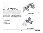
Transport motor 1, MOT12-223, is a stepper motor located on the rear frame. The output shaft
of the motor drives a toothed timing belt, that transfers mechanical drive to two sets of nip rolls
in the entrance paper path. Refer to
Figure 1
.
Diverter Gate
Sheets continue up the entrance paper path, by way of two sets of nip rolls, to the diverter gate.
The diverter gate is opened by the diverter gate solenoid, SOL 12-225.
If the diverter gate is open, the sheets are diverted to bin 0. If the diverter gate is closed, sheets
continue to the vertical paper transport. Refer to
Figure 1
.
Bin 0
Bin 0 receives all transparency jobs, label jobs and all jobs not selected by the operator to be
made into compiled sets or compiled and stapled sets.
Bin 0 Paper Path and Transport Motor 2
Transport motor 2, MOT12-224, is a stepper motor located on the rear frame. The output shaft
of the motor drives a toothed timing belt, that transfers mechanical drive to the driven compo-
nents in the upper paper path. Sheets leaving the vertical transport via the opened upper
diverter gate are transported to bin 0 by the upper paper path. Refer to
Figure 1
.
Bin 0 Operation
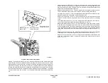
Top exit sensor, Q12-107 is used to detect jams in the bin 0 area. When the trail edge clears
the top exit sensor it signals the control logic that the sheet has exited the upper paper path.
Sheet edge detection is disabled until just before either edge is expected (approx. 30 mm).
This is done to avoid reading false signals caused by sensor bounce.
As the paper is ejected, it drops vertically to the bin 0 surface. Subsequent sheets settle on top
of the previous sheets, creating a stack.
Vertical Paper Transport
The vertical paper transport is used to feed the printed sheets to the compiler.
Compiler Carriage
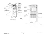
The sheets are transported through the vertical transport by two sets of nip rolls, powered via
toothed timing belts from transport motor 1, MOT12-223. Refer to
Figure 1
.
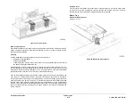
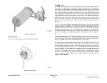
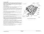
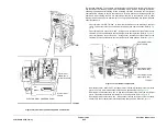
Sheets arrive at the compiler tray and are reversed against the backstops by the combined
action of the angle of the compiler tray and the rotation of the paddle wheel. The paddle wheel
is driven by the paddle roll motor, MOT12-237. The paddle wheel position is set by the paddle
roll position sensor, Q12-186, adjacent to the motor.
As each sheet is registered against the backstops, it is tamped to ensure a neat set. When the
set is complete it is stapled, if required, before being ejected into bin 1.
The eject assembly then ejects the set into the stacker tray.
Compiler Stapler Operation
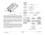
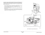
The purpose of the compiler carriage stapler is to staple the compiled sets in the compiler tray.
Up to 50 sheets of (80gsm / 20lb) paper can be stapled. Single or double stapling is available in
portrait or landscape mode, corner stapling is also available.
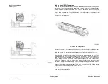
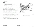
The staple head unit 1 assembly is mounted on the stapler mount and traverse shaft, which
moves the stapler to the various stapling positions within the compiler. Drive is provided by the
stapling unit traverse motor, MOT 12-249 which drives the stapler mount and traverse shaft
assembly, to position the stapler. The stapling unit home sensor, Q12-135 senses when the
stapler is at the home position.
Once the signal has been received to staple, the staple head 1 motor, MOT 12-247 (located
within the staple head) is energized. The motor remains energized until the cam has made a
complete revolution and the SH1 home sensor, Q12-318 has been actuated. The one revolu-
tion of the cam enables a staple to be driven though the set, clinched, and then return the sta-
ple head to the home (open) position for the next staple.
Stapler Unit 1 Home Sensor
The stapling unit (SU1) home sensor, Q12-135 is located at the front of the compiler carriage.
All stapler traverse positions are calculated using this home reference.
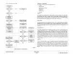
When the stapler transport is started for the first time the 2K LCSS PWB starts the stapling unit
traverse motor, MOT12-249, towards the rear for 200 steps. After this movement, the motor is
stopped and driven towards the front until the home sensor is detected. This is the home posi-
tion, and all traverse values for stapling positions are relative to it.
Stapler Unit Transverse Motor
The stapler transport consists of a linear slide and traverse shaft assembly which is driven by
the stapling unit traverse motor, MOT12-249. The transport system positions the stapler at the
various positions necessary for the stapling operation.
Summary of Contents for ColorQube 9303 Series
Page 1: ...Xerox ColorQube 9303 Family Service Manual 708P90290 February 2013...
Page 4: ...February 2013 ii ColorQube 9303 Family Introduction...
Page 18: ...February 2013 1 2 ColorQube 9303 Family Service Call Procedures...
Page 92: ...February 2013 2 68 ColorQube 9303 Family 05F Status Indicator RAPs...
Page 104: ...February 2013 2 80 ColorQube 9303 Family 12 701 00 65 Status Indicator RAPs...
Page 200: ...February 2013 2 176 ColorQube 9303 Family 12N 171 Status Indicator RAPs...
Page 292: ...February 2013 2 268 ColorQube 9303 Family 16D Status Indicator RAPs...
Page 320: ...February 2013 2 296 ColorQube 9303 Family 42 504 00 42 505 00 Status Indicator RAPs...
Page 500: ...February 2013 2 476 ColorQube 9303 Family 94B Status Indicator RAPs...
Page 648: ...February 2013 3 2 ColorQube 9303 Family Image Quality...
Page 653: ...February 2013 3 7 ColorQube 9303 Family IQ 1 Image Quality Figure 1 IQ defects 1...
Page 654: ...February 2013 3 8 ColorQube 9303 Family IQ 1 Image Quality Figure 2 IQ defects 2...
Page 655: ...February 2013 3 9 ColorQube 9303 Family IQ 1 Image Quality Figure 3 IQ defects 3...
Page 656: ...February 2013 3 10 ColorQube 9303 Family IQ 1 Image Quality Figure 4 IQ defects 4...
Page 657: ...February 2013 3 11 ColorQube 9303 Family IQ 1 Image Quality Figure 5 IQ defects 5...
Page 658: ...February 2013 3 12 ColorQube 9303 Family IQ 1 Image Quality Figure 6 IQ defects 6...
Page 660: ...February 2013 3 14 ColorQube 9303 Family IQ 1 Image Quality Figure 9 IQ defects 9...
Page 661: ...February 2013 3 15 ColorQube 9303 Family IQ 1 Image Quality Figure 10 IQ defects 10...
Page 662: ...February 2013 3 16 ColorQube 9303 Family IQ 1 Image Quality Figure 11 IQ defects 11...
Page 663: ...February 2013 3 17 ColorQube 9303 Family IQ 1 Image Quality Figure 12 IQ defects 12...
Page 664: ...February 2013 3 18 ColorQube 9303 Family IQ 1 Image Quality Figure 13 IQ defects 13...
Page 728: ...February 2013 3 82 ColorQube 9303 Family IQ 29 IQ 30 Image Quality...
Page 736: ...February 2013 3 90 ColorQube 9303 Family TP 15 Image Quality Figure 2 Media path test pages...
Page 758: ...February 2013 3 112 ColorQube 9303 Family IQS 7 IQS 8 Image Quality...
Page 778: ...February 2013 4 20 ColorQube 9303 Family REP 1 9 Repairs Adjustments...
Page 794: ...February 2013 4 36 ColorQube 9303 Family REP 3 10 Repairs Adjustments...
Page 1144: ...February 2013 4 386 ColorQube 9303 Family REP 94 1 Repairs Adjustments...
Page 1176: ...February 2013 4 418 ColorQube 9303 Family ADJ 62 3 ADJ 62 4 Repairs Adjustments...
Page 1182: ...February 2013 4 424 ColorQube 9303 Family ADJ 75 3 Repairs Adjustments...
Page 1184: ...February 2013 4 426 ColorQube 9303 Family ADJ 82 1 Repairs Adjustments...
Page 1186: ...February 2013 4 428 ColorQube 9303 Family ADJ 91 1 Repairs Adjustments...
Page 1552: ...February 2013 6 260 ColorQube 9303 Family dC140 General Procedures Information...
Page 1576: ...February 2013 6 284 ColorQube 9303 Family dC640 General Procedures Information...
Page 1578: ...February 2013 6 286 ColorQube 9303 Family dC708 dC715 General Procedures Information...
Page 1600: ...February 2013 7 2 ColorQube 9303 Family Wiring Data...
Page 1696: ...February 2013 8 2 ColorQube 9303 Family Principles of Operation...
Page 1808: ...February 2013 8 114 ColorQube 9303 Family Principles of Operation...
Page 1809: ...XEROX EUROPE...
Page 1810: ...XEROX EUROPE...
Page 1811: ...XEROX EUROPE...
Page 1812: ...XEROX EUROPE...

