February 2013
6-279
ColorQube® 9303 Family
dC335, dC361
General Procedures/Information
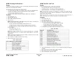
The ink melt plate heaters only have options for On and Off as listed in
Table 2
.
NOTE: The ink melt heater Setpoint Mode for On is displayed as 120 degrees C. This is a tar-
get temperature only. The heater will turn on for a few seconds each time it is activated. It is not
intended to reach 120 degrees. Due to the risk of overflow if the ink melt is continuously acti-
vated the software will ignore the command.
Procedure
1.
Enter service mode,
GP 1
.
2.
Select the Diagnostics tab.
3.
Select dC335 Heater Monitor and Exerciser.
The screen displays a blank graph with options to select the required component.
4.
Select a component from the menu at the bottom left of the screen.
As each component is selected the corresponding buttons will change to match the
options for that component.
NOTE: If the setpoint mode of any of the printhead heaters (reservoir, left jetstack or right jet-
stack) is changed, the other two heaters will change to the same setpoint mode automatically.
This is to ensure that the printhead is not subjected to undue stress due to temperature varia-
tion between the different heaters.
5.
Select the component and options required.
6.
Select the Graph button
•
The graph will display a trace indicating the temperature change in real time.
•
The green line indicates the time.
•
The blue line indicates the current temperature.
•
The yellow line indicates the target temperature.
7.
To view the graph in more detail, touch the UI to zoom in. Touch the screen again to zoom
out.
8.
Analyze the results and take the appropriate action as required.
9.
Select stop to finish monitoring the temperature of the component.
10. Select Close to return to the service mode window.
11.
Select Call Closeout to exit service mode.
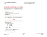
dC361 NVM Save and Restore
Purpose
To restore the NVM parameters of the machine to their previous values following a service
action; i.e. NVM expansion, Single Board Controller (SBC) Printed Wiring Board (PWB)
replacement, or any others that would necessitate a full NVM initialization. It can also be used
to recover a machine‘s NVM values to a recent service call, in the event that a complete NVM
failure occurred. As an additional tool, the ability to copy files between the hard drive and a
USB drive is provided.
The NVM save to hard disk must be performed at the first service call and whenever the sys-
tem software is changed.
This procedure will save and restore only the SBC, IIT and IME NVM.
NOTE: After a USB flash drive is first connected to the machine a UI sceen message offering
scan to and print from USB options will display. This screen message can be closed or left
open before entering diagnostics without effecting the NVM save / restore processes. If you
choose to close the scan to and print from USB screen message it will not reappear on exit
from diagnostics. Therefore, leave this message screen open if the scan to and print from USB
options are to be required after a NVM save / restore.
Procedure
NVM Save
1.
If necessary, connect the USB flash drive to the USB port on the left side of the machine.
2.
Enter service mode,
GP 1
.
3.
Select the Adjustments tab.
4.
Select dC361 NVM Save and Restore.
The screen displays the NVM data.
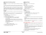
NOTE:
•
The top entry displays the live NVM data for the machine.
•
If the data has previously been saved to the hard disk these will be displayed in a list
below the live data.
•
If a USB device containing NVM data is connected these will be displayed below the
hard disk data. To be recognized by the machine the USB device must be connected
at the time dC361 is started.
5.
Save the NVM data.
•
To save the live data to the hard disk select the live data entry and select save to
hard disk.
•
To save the hard disk data to a USB device select the hard disk entry and select
save to USB device.
•
To save the USB data to the hard disk select the USB entry and select save to HDD.
NOTE: Data cannot be saved or restored directly to or from the USB device to the
machine.
6.
Select Close to return to the service mode window.
7.
Select Call Closeout to exit service mode
Table 2 Ink Melt Temperatures
Component
Setpoint on
Setpoint off
Ink melt Y
120 C
Ambient
Ink melt M
120 C
Ambient
Ink melt C
120 C
Ambient
Ink melt K
120 C
Ambient
Summary of Contents for ColorQube 9303 Series
Page 1: ...Xerox ColorQube 9303 Family Service Manual 708P90290 February 2013...
Page 4: ...February 2013 ii ColorQube 9303 Family Introduction...
Page 18: ...February 2013 1 2 ColorQube 9303 Family Service Call Procedures...
Page 92: ...February 2013 2 68 ColorQube 9303 Family 05F Status Indicator RAPs...
Page 104: ...February 2013 2 80 ColorQube 9303 Family 12 701 00 65 Status Indicator RAPs...
Page 200: ...February 2013 2 176 ColorQube 9303 Family 12N 171 Status Indicator RAPs...
Page 292: ...February 2013 2 268 ColorQube 9303 Family 16D Status Indicator RAPs...
Page 320: ...February 2013 2 296 ColorQube 9303 Family 42 504 00 42 505 00 Status Indicator RAPs...
Page 500: ...February 2013 2 476 ColorQube 9303 Family 94B Status Indicator RAPs...
Page 648: ...February 2013 3 2 ColorQube 9303 Family Image Quality...
Page 653: ...February 2013 3 7 ColorQube 9303 Family IQ 1 Image Quality Figure 1 IQ defects 1...
Page 654: ...February 2013 3 8 ColorQube 9303 Family IQ 1 Image Quality Figure 2 IQ defects 2...
Page 655: ...February 2013 3 9 ColorQube 9303 Family IQ 1 Image Quality Figure 3 IQ defects 3...
Page 656: ...February 2013 3 10 ColorQube 9303 Family IQ 1 Image Quality Figure 4 IQ defects 4...
Page 657: ...February 2013 3 11 ColorQube 9303 Family IQ 1 Image Quality Figure 5 IQ defects 5...
Page 658: ...February 2013 3 12 ColorQube 9303 Family IQ 1 Image Quality Figure 6 IQ defects 6...
Page 660: ...February 2013 3 14 ColorQube 9303 Family IQ 1 Image Quality Figure 9 IQ defects 9...
Page 661: ...February 2013 3 15 ColorQube 9303 Family IQ 1 Image Quality Figure 10 IQ defects 10...
Page 662: ...February 2013 3 16 ColorQube 9303 Family IQ 1 Image Quality Figure 11 IQ defects 11...
Page 663: ...February 2013 3 17 ColorQube 9303 Family IQ 1 Image Quality Figure 12 IQ defects 12...
Page 664: ...February 2013 3 18 ColorQube 9303 Family IQ 1 Image Quality Figure 13 IQ defects 13...
Page 728: ...February 2013 3 82 ColorQube 9303 Family IQ 29 IQ 30 Image Quality...
Page 736: ...February 2013 3 90 ColorQube 9303 Family TP 15 Image Quality Figure 2 Media path test pages...
Page 758: ...February 2013 3 112 ColorQube 9303 Family IQS 7 IQS 8 Image Quality...
Page 778: ...February 2013 4 20 ColorQube 9303 Family REP 1 9 Repairs Adjustments...
Page 794: ...February 2013 4 36 ColorQube 9303 Family REP 3 10 Repairs Adjustments...
Page 1144: ...February 2013 4 386 ColorQube 9303 Family REP 94 1 Repairs Adjustments...
Page 1176: ...February 2013 4 418 ColorQube 9303 Family ADJ 62 3 ADJ 62 4 Repairs Adjustments...
Page 1182: ...February 2013 4 424 ColorQube 9303 Family ADJ 75 3 Repairs Adjustments...
Page 1184: ...February 2013 4 426 ColorQube 9303 Family ADJ 82 1 Repairs Adjustments...
Page 1186: ...February 2013 4 428 ColorQube 9303 Family ADJ 91 1 Repairs Adjustments...
Page 1552: ...February 2013 6 260 ColorQube 9303 Family dC140 General Procedures Information...
Page 1576: ...February 2013 6 284 ColorQube 9303 Family dC640 General Procedures Information...
Page 1578: ...February 2013 6 286 ColorQube 9303 Family dC708 dC715 General Procedures Information...
Page 1600: ...February 2013 7 2 ColorQube 9303 Family Wiring Data...
Page 1696: ...February 2013 8 2 ColorQube 9303 Family Principles of Operation...
Page 1808: ...February 2013 8 114 ColorQube 9303 Family Principles of Operation...
Page 1809: ...XEROX EUROPE...
Page 1810: ...XEROX EUROPE...
Page 1811: ...XEROX EUROPE...
Page 1812: ...XEROX EUROPE...


