


February 2013
8-74
ColorQube® 9303 Family
Principles of Operation
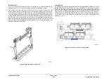
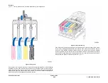
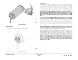
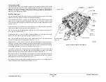
The IOD module enables a variety of system functions on the ColorQube. Its primary function
is to align the four printheads to create a seamless image. This is called head-to-head align-
ment, or H2H alignment. A second function is to adjust the jetting intensity of the heads, again
to maintain consistent intensity across the entire image. This is called head-to-head intensity,
or H2H intensity. Intensity for the whole printhead is set at once, jets cannot be individually
adjusted for intensity. A third function is to detect and correct weak and missing jets by substi-
tution, a process known as jet masking.
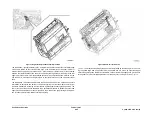
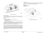
IOD Operational Sequence
The IOD sequence is only performed from standby state. The IOD sequence typically occurs
every 500 pages. The printer stops and performs an IOD rear scan then waits another 500
pages and performs IOD front scan. Scans continue to alternate between rear and front every
500 pages. Manually activated scans are executed from diagnostics. The technician selects
either a front or rear IOD scan.
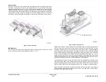
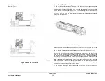
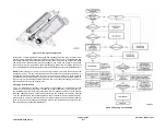
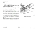
When an IOD sequence is executed, the following steps are performed:
1.
A drum maintenance cycle is performed to prepare the drum for imaging.
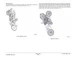
2.
The scan bar is moved to the rear (or front) position. The unmarked drum surface is read
with and without illumination to establish black and white calibration levels. This is done
while the drum is rotating, so that an average is achieved. After calibration, the scan bar
moves to the park position, which is the approximate center of travel of the IOD assembly.
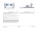
3.
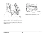
The target image is jetted onto the drum.
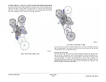
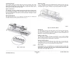
4.
The scan bar is moved to the rear (or front) position. A snapshot of the image is acquired
by the IOD by rotating the drum with the target image across the scan bar. After the IOD
has acquired the image, the scan bar is protected and then moved to the park position.
5.
The acquired target is analyzed to calculate head position.
6.
Appropriate head position corrections are calculated and applied. There are four types of
corrections:
•
Each printhead has a small motor to adjust printhead rotation in the radial axis. The
IOD correction step immediately moves these motors.
•
Each printhead has a Y-axis offset value from the drum home position that controls
jet timing for all jets on that head during imaging. The IOD correction step updates
these Y-offset values.
•
Each SFWA has an X-Axis offset value from the SFWA home position that controls
the starting position of the SFWAs during imaging. The IOD correction step updates
these X-offset values.
•
Each SFWA has a head that is fixed, and a second head with a small motor to adjust
X-position relative to the fixed head. The IOD correction step immediately moves
these motors.
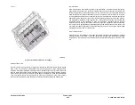
7.
A cleaning unit cycle is performed to scrape the target image from the drum.
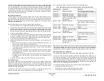
IOD Sequence Types
Since the IOD cannot see one of the printheads during a scan, it is unable to correct head
alignment for all four heads in one scan sequence. In its present form, the IOD system is only
able to correct printhead alignment based on what it sees during that sequence. Also, it does
not retain scan data to be interpreted by a subsequent scan sequence to provide a single
adjustment covering all printheads.
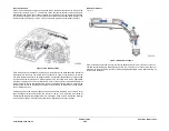
The IOD has no home sensor. It drives fully in one direction until it stalls and assumes it is fully
forward or rearward. Then it counts clock pulses to the central park position.
Table 1
Measurement and corrective Actions for Front and Rear IOD Scans
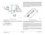
IOD reads drum run out at home (from the drum encoder) and at 6 degree intervals. These val-
ues are stored and used to set Y axis run out variance of timing of the jets on the printheads.
This calibration should be performed whenever the drum encoder is serviced (which may
change the home position) or whenever the drum is changed (which will change the run out).
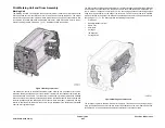
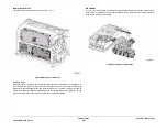
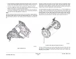
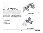
IOD Printhead efficiency maintenance
The efficiency of the printheads is measured by Closed Loop Dropmass (CLD) calibration.
There are two CLD measurement processes, cldBaseline and cldAdjust. The cldBaseline pro-
cess measures the efficiency of each printhead when it is first installed onto a printer (time
zero). The value of the cldBaseline measurement is stored in the machines NVRAM. The cld-
Adjust process measures the efficiency of each printhead periodically over it’s life time, and
applies incremental head-drive voltage adjustments to maintain the original printhead effi-
ciency captured by the cldBaseline process at time zero.
The cldAdjust and cldBaseline process are similar and include the following steps;
•
Calibration of the IOD scanbar sensor.
•
Render and print measurement target into the drum surface.
•
Scan an image of the drum surface using the IOD scan bar.
Table 1 Measurement and Correction Actions for Front and Rear IOD Scans
Head Positions
Front Scan
Rear Scan
Head 1 Roll
Measure and adjust.
Cannot be measured during a rear
scan. Adjustment cannot be performed.
Head 2 Roll
Measure. Do not adjust.
Measure and adjust.
Head 3 Roll
Measure. Do not adjust.
Measure and adjust.
Head 4 Roll
Cannot be measured during a
front scan. Adjustment cannot
be performed.
Measure and adjust.
Head 1 Y-offset
Measure and adjust.
Cannot be measured during a rear
scan. Adjust as if stitched to printhead
2.
Head 2 Y-offset
Measure. Do not adjust.
Measure and adjust.
Head 3 Y-offset
Anchor.
Anchor.
Head 4 Y-offset
Cannot be measured during a
front scan. Adjustment cannot
be performed.
Measure and adjust.
Head 1 X-stitch
Measure and adjust.
Cannot be measured during a rear
scan. Adjust as if stitched to printhead
2.
Head 2 X-stitch
Measure. Do not adjust.
Measure and adjust.
Head 3 X-stitch
Anchor.
Anchor.
Head 4 X-stitch
Cannot be measured during a
front scan, Adjustment cannot
be performed.
Measure and adjust.
Summary of Contents for ColorQube 9303 Series
Page 1: ...Xerox ColorQube 9303 Family Service Manual 708P90290 February 2013...
Page 4: ...February 2013 ii ColorQube 9303 Family Introduction...
Page 18: ...February 2013 1 2 ColorQube 9303 Family Service Call Procedures...
Page 92: ...February 2013 2 68 ColorQube 9303 Family 05F Status Indicator RAPs...
Page 104: ...February 2013 2 80 ColorQube 9303 Family 12 701 00 65 Status Indicator RAPs...
Page 200: ...February 2013 2 176 ColorQube 9303 Family 12N 171 Status Indicator RAPs...
Page 292: ...February 2013 2 268 ColorQube 9303 Family 16D Status Indicator RAPs...
Page 320: ...February 2013 2 296 ColorQube 9303 Family 42 504 00 42 505 00 Status Indicator RAPs...
Page 500: ...February 2013 2 476 ColorQube 9303 Family 94B Status Indicator RAPs...
Page 648: ...February 2013 3 2 ColorQube 9303 Family Image Quality...
Page 653: ...February 2013 3 7 ColorQube 9303 Family IQ 1 Image Quality Figure 1 IQ defects 1...
Page 654: ...February 2013 3 8 ColorQube 9303 Family IQ 1 Image Quality Figure 2 IQ defects 2...
Page 655: ...February 2013 3 9 ColorQube 9303 Family IQ 1 Image Quality Figure 3 IQ defects 3...
Page 656: ...February 2013 3 10 ColorQube 9303 Family IQ 1 Image Quality Figure 4 IQ defects 4...
Page 657: ...February 2013 3 11 ColorQube 9303 Family IQ 1 Image Quality Figure 5 IQ defects 5...
Page 658: ...February 2013 3 12 ColorQube 9303 Family IQ 1 Image Quality Figure 6 IQ defects 6...
Page 660: ...February 2013 3 14 ColorQube 9303 Family IQ 1 Image Quality Figure 9 IQ defects 9...
Page 661: ...February 2013 3 15 ColorQube 9303 Family IQ 1 Image Quality Figure 10 IQ defects 10...
Page 662: ...February 2013 3 16 ColorQube 9303 Family IQ 1 Image Quality Figure 11 IQ defects 11...
Page 663: ...February 2013 3 17 ColorQube 9303 Family IQ 1 Image Quality Figure 12 IQ defects 12...
Page 664: ...February 2013 3 18 ColorQube 9303 Family IQ 1 Image Quality Figure 13 IQ defects 13...
Page 728: ...February 2013 3 82 ColorQube 9303 Family IQ 29 IQ 30 Image Quality...
Page 736: ...February 2013 3 90 ColorQube 9303 Family TP 15 Image Quality Figure 2 Media path test pages...
Page 758: ...February 2013 3 112 ColorQube 9303 Family IQS 7 IQS 8 Image Quality...
Page 778: ...February 2013 4 20 ColorQube 9303 Family REP 1 9 Repairs Adjustments...
Page 794: ...February 2013 4 36 ColorQube 9303 Family REP 3 10 Repairs Adjustments...
Page 1144: ...February 2013 4 386 ColorQube 9303 Family REP 94 1 Repairs Adjustments...
Page 1176: ...February 2013 4 418 ColorQube 9303 Family ADJ 62 3 ADJ 62 4 Repairs Adjustments...
Page 1182: ...February 2013 4 424 ColorQube 9303 Family ADJ 75 3 Repairs Adjustments...
Page 1184: ...February 2013 4 426 ColorQube 9303 Family ADJ 82 1 Repairs Adjustments...
Page 1186: ...February 2013 4 428 ColorQube 9303 Family ADJ 91 1 Repairs Adjustments...
Page 1552: ...February 2013 6 260 ColorQube 9303 Family dC140 General Procedures Information...
Page 1576: ...February 2013 6 284 ColorQube 9303 Family dC640 General Procedures Information...
Page 1578: ...February 2013 6 286 ColorQube 9303 Family dC708 dC715 General Procedures Information...
Page 1600: ...February 2013 7 2 ColorQube 9303 Family Wiring Data...
Page 1696: ...February 2013 8 2 ColorQube 9303 Family Principles of Operation...
Page 1808: ...February 2013 8 114 ColorQube 9303 Family Principles of Operation...
Page 1809: ...XEROX EUROPE...
Page 1810: ...XEROX EUROPE...
Page 1811: ...XEROX EUROPE...
Page 1812: ...XEROX EUROPE...


