background image

MAC215990

151

Revision A

Checking and adjusting sensor output voltage

DANGER

Ensure that all bystanders have cleared the area.

4.

Engage the parking brake.

IMPORTANT:

To measure the output voltage of the fore-aft sensor, the engine needs to be running and supplying power to the
sensor.

5.

Start the engine.

1032692

A

B

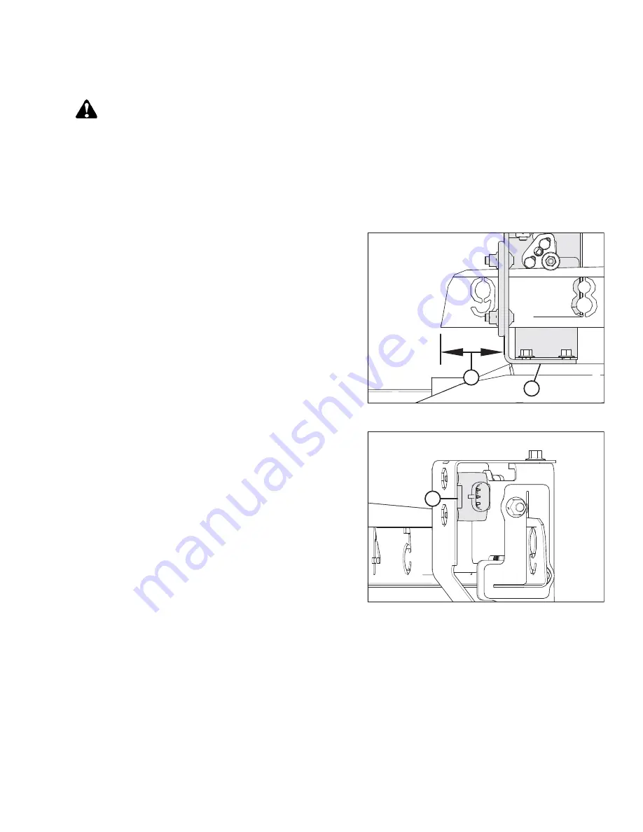
Figure 3.169: Fore-Aft Bracket

6.

Adjust the reel to the fully forward position. Ensure that
dimension (B) (from the sensor bracket to the end of the
indicator) is 62

72 mm (2.4

2.8 in.).

1032694

A

1
2
3

Figure 3.170: Fore-Aft Sensor

7.

Use the combine display or a voltmeter (if measuring the
sensor manually) to measure the voltage range. If using a
voltmeter, check sensor voltage (A) between pin 2 (ground)
and pin 3 (signal).

For Case and New Holland combines, the voltage range
should be 0.7

1.1 V

8.

Shut down the engine, and remove the key from
the ignition.

OPERATION

Summary of Contents for NEW HOLLAND D2 Series

Page 1: ...D2 Series Draper Header with FM200 Float Module Operator s Manual MAC215990 Revision A Original Instruction...

Page 2: ...is based on the information available and in effect at the time of printing MacDon Industries Ltd makes no representation or warranty of any kind whether expressed or implied with respect to the infor...

Page 3: ...QLWRED DQDGD 5 6 d W E t D d E D E E K E K W E Z D D t K E K E K D t s D E K E K E K E Z D t d t W D E D s Z E K E K K E h W E W h Z D D t E d E E E K E K E Z D t d D E m E K E K d Z W D t D W d E E K...

Page 4: ...E t s D E Z E K E K W E E Z D t WK D K d E E t E K E K Z D t E ZK E d E E K E K E Z D D t s s D E E K E K W E Z D t d D s h E K E K Z D t E D d E s W E K E K D D D Z D t E d E d E E h E K E K E E Z D...

Page 5: ...D W E t D d E D E E K E K W E Z D D t K E K E K D t s D E K E K E K E Z D t d t W D E D s Z E K E K K E h W E W h Z D D t E d E E E K E K E Z D t d D E m E K E K d Z W D t D W d E E K E K D Z D t E Z...

Page 6: ...E t s D E Z E K E K W E E Z D t WK D K d E E t E K E K Z D t E ZK E d E E K E K E Z D D t s s D E E K E K W E Z D t d D s h E K E K Z D t E D d E s W E K E K D D D Z D t E d E d E E h E K E K E E Z D...

Page 7: ...0DF RQ QGXVWULHV WG 0RUD 6WUHHW LQQLSHJ 0DQLWRED DQDGD 5 6 D d W t D d E D E D Z E K E K W h MAC215990 v Revision A...

Page 8: ...0DF RQ QGXVWULHV WG 0RUD 6WUHHW LQQLSHJ 0DQLWRED DQDGD 5 6 D D D D W t D d E D E D Z E K E K W h MAC215990 vi Revision A...

Page 9: ...accordance with the manufacturer s instructions Your manual Carefully read all the material provided before attempting to use the machine Use this manual as your first source of information about the...

Page 10: ...t the rear of the header beside the right outer leg NOTE Keep your MacDon publications up to date The most current English version can be downloaded from our website www macdon com or from our Dealer...

Page 11: ...cated on the back of the header beside the left endsheet 1028872 A Figure 3 Float Module Serial Number Plate Location FM200 Float Module for Combine Serial Number Model Year The float module s serial...

Page 12: ......

Page 13: ...ensions 30 2 4 D2 Series Draper Header 31 2 5 FM200 Float Module Component Identification 32 Chapter 3 Operation 35 3 1 Owner Operator Responsibilities 35 3 2 Operational Safety 36 3 2 1 Header Safety...

Page 14: ...ing Feed Auger Fingers 109 3 8 4 Setting Auger Position 111 3 8 5 Checking and Adjusting Feed Auger Springs 113 3 8 6 Stripper Bars 114 3 9 Header Operating Variables 115 3 9 1 Cutting off Ground 115...

Page 15: ...Series 189 Header Settings Quick Reference New Holland CR Series 191 Setting up Auto Header Height Control New Holland CR and CX Series 192 Calibrating Auto Header Height Control New Holland CR and CX...

Page 16: ...4 2 4 Equipment Servicing End of Season 246 4 2 5 Checking Hydraulic Hoses and Lines 247 4 3 Lubrication 248 4 3 1 Lubrication Intervals 248 Every 10 Hours 248 Every 25 Hours 249 Every 50 Hours 250 Ev...

Page 17: ...stalling Knifehead Bearing 309 4 8 5 Installing Knife 310 4 8 6 Spare Knives 312 4 8 7 Pointed Knife Guards and Hold Downs 312 Pointed Knife Guard Configuration on Single Knife Headers 314 Pointed Kni...

Page 18: ...sing Feed Deck Pan 364 4 10 7 Checking Link Holder Hooks 365 4 11 Stripper Bars 368 4 11 1 Removing Stripper Bars 368 4 11 2 Installing Stripper Bars 368 4 11 3 Replacing Feeder Deflectors on New Holl...

Page 19: ...peed Kit Installed 425 4 14 4 Double Reel Drive U Joint 426 Removing Double Reel Drive U Joint 426 Installing Double Reel U Joint 427 4 14 5 Reel Drive Motor 428 Removing Reel Drive Motor 428 Installi...

Page 20: ...458 5 4 3 Outboard Steel End Finger Kit 459 5 4 4 Steel Reel Finger Kit 459 5 4 5 Side Hill Stabilizer Kit 460 5 4 6 Stabilizer Wheel Kit 460 5 4 7 Steel Skid Shoes Kit 461 Chapter 6 Troubleshooting 4...

Page 21: ...ty Alert Symbols The safety alert symbol indicates important safety messages in this manual and on safety signs on the machine 1000915 Figure 1 1 Safety Symbol This symbol means ATTENTION BECOME ALERT...

Page 22: ...ill result in death or serious injury WARNING Indicates a potentially hazardous situation that if it is not prevented could result in death or serious injury It may also be used to alert you to unsafe...

Page 23: ...ive footwear with slip resistant soles Protective glasses or goggles Heavy gloves Wet weather gear Respirator or filter mask 1000005 Figure 1 3 Safety Equipment In addition take the following precauti...

Page 24: ...the functionality and or safety of the machine It may also shorten the machine s service life To avoid injury or death from the unexpected startup of the machine ALWAYS stop the engine and remove the...

Page 25: ...Keep the work area well lit 1008958 Figure 1 9 Equipment is NOT Safe for Children Relieve pressure from hydraulic circuits before servicing and or disconnecting the machine Ensure that all components...

Page 26: ...MAC215990 6 Revision A 1000004 Figure 1 10 Personal Protective Equipment Wear protective gear when working on the machine Wear heavy gloves when working on knife components SAFETY...

Page 27: ...es fittings or hoses by using tapes clamps cements or welding The hydraulic system operates under extremely high pressure Makeshift repairs can fail suddenly and create hazardous conditions 1001207 Fi...

Page 28: ...repair shop if necessary Ensure that the tire is correctly seated on the rim before inflating it If the tire is not correctly positioned on the rim or is overinflated the tire bead can loosen on one...

Page 29: ...such as lubricants refrigerants and fuels and hazardous materials found in batteries some light bulbs and electronic equipment must be handled safely and not introduced into the environment Comply wit...

Page 30: ...electrical systems Recycle or reuse packaging material Recycle or reuse plastics that are labelled with specifications for a material such as PP TV 20 Do NOT dispose of them with domestic waste Return...

Page 31: ...l part on which a safety sign was installed is replaced ensure that the repair part displays the current safety sign Replacement safety signs are available from your Dealer 1 8 1 Installing Safety Dec...

Page 32: ...re placed on the machine where there is a risk of personal injury or where the operator has to take extra precaution before operating controls 1036745 A B Figure 1 19 Reel Arms and Endsheets A MAC3605...

Page 33: ...evision A A A B B C C D D Figure 1 20 Backtube A MAC313725 Read Manual High Pressure Fluid Header Hazard B MAC174436 High Pressure Fluid Hazard C MAC311493 Center Prop Lock D MAC313733 Header Crushing...

Page 34: ...Revision A A A B B Figure 1 21 FM200 Float Module A MAC313728 Read Manual Fluid Spray Hazard B MAC360655 Released Spring Energy Hazard 1029300 A A A Figure 1 22 Upper Cross Auger A MAC279085 Auger Wa...

Page 35: ...15 Revision A 1032196 A A Figure 1 23 EasyMove Transport System Tow Bar Short Bar Shown Long Bar Similar A MAC327588 Hitch Damage Hazard 1031139 A A Figure 1 24 Vertical Knife A MAC313881 Knife Hazar...

Page 36: ...MAC215990 16 Revision A A A Figure 1 25 Stabilizer Wheels A MAC327086 Released Spring Energy Hazard SAFETY...

Page 37: ...ressure in the hydraulic system before loosening any hydraulic fittings If you are injured seek emergency medical help IMMEDIATE surgery is required to remove hydraulic fluid which has penetrated the...

Page 38: ...93 MAC311493 Reel crushing hazard DANGER To prevent injury from the fall of a raised reel fully raise the reel Stop the engine and remove the key and engage the mechanical safety lock on each reel sup...

Page 39: ...p the engine and remove the key from the ignition before servicing adjusting lubricating cleaning or unplugging the machine Engage the safety locks to prevent lowering of raised unit before servicing...

Page 40: ...ing operation Keep riders off of the machine Keep all shields in place and stay clear of moving parts Disengage the header drive put the transmission in Neutral and wait for all movement to stop befor...

Page 41: ...prevent injury or death from the fall of a raised header Fully raise the header stop the engine remove the key and engage the mechanical safety locks on the combine before going under the header Alter...

Page 42: ...ring operation Keep riders off of the machine Keep all shields in place and stay clear of moving parts Disengage the header drive put the transmission in Neutral and wait for all movement to stop befo...

Page 43: ...r has counterweight and becomes energized Do NOT attempt to pry adjustment handle out of a position slot before releasing tension from the assist springs 1032194 Figure 1 35 MAC327588 MAC327588 Hitch...

Page 44: ...rm before working on or under the reel 360655 1039295 Figure 1 37 MAC360655 MAC360655 Released spring energy hazard DANGER To prevent serious injury or death from the fall of a raised implement After...

Page 45: ...n in which the given sealing surfaces or components are making contact with each other and the fitting has been tightened by hand to a point where the fitting is no longer loose and cannot be tightene...

Page 46: ...lley or sprocket TFFT Turns from finger tight Timed knife drive Synchronized motion applied at cutterbar to two separately driven knives from a single hydraulic motor Torque The product of a force the...

Page 47: ...width For the effective cutting width see the Cutterbar section Effective cut width minus 76 mm 3 in Knife Single knife drive 7 6 10 7 m 25 35 ft One hydraulic motor mounted to an enclosed heavy duty...

Page 48: ...s All header sizes Plastic wear plates across the full width of cutterbar S 7 6 m 25 ft headers 4 plastic skid shoes with steel support structure S 9 1 13 7 m 30 45 ft headers 6 skid shoes with steel...

Page 49: ...THF viscosity at 100 C 212 F 9 5 cSt Upper Cross Auger OD Outside diameter 330 mm 13 in Tube diameter 152 mm 6 in Stabilizer Wheel EasyMove Transport OD Wheels 38 cm 15 in Tires 225 75 R 15 Header We...

Page 50: ...page 30 2591 mm 102 in Header width in transport position with FM200 installed shortest center link Dimension B shows the gearbox in operating position with standard crop dividers installed Refer to F...

Page 51: ...ructions provided A B C D F E G H J K L M N Figure 2 2 D2 Series Draper Header Double Reel Shown A Pick Up Reel B Reel Cam C Divider Cone Divider Rod Not Shown D Endshield E Reel Lift Cylinder F Reel...

Page 52: ...make it easier to follow the operation and maintenance instructions provided in this manual 1029303 A B B C D E F G G H J Figure 2 3 Header Side of FM200 Float Module A Feed Auger B Header Float Sprin...

Page 53: ...odule A Main Gearbox B Completion Gearbox C Reservoir Oil Level Sight Glass D Center Link E Header Height Control Indicator x2 F Bubble Level G Drain Plug x2 H Float Lock Handle x2 J Auto Header Heigh...

Page 54: ......

Page 55: ...he people around you Before allowing people to operate the header for however short a time or distance make sure they have been instructed in its safe and proper use Review the manual and all safety r...

Page 56: ...sure to keep the transmission in gear when travelling downhill Never attempt to get on or off a moving machine Do NOT leave the operator s station while the engine is running To avoid bodily injury or...

Page 57: ...prevent the reel from unexpectedly lowering DANGER To prevent injury or death from the unexpected start up of the machine always stop the engine and remove the key from the ignition before leaving the...

Page 58: ...on of the reel and header disengage the reel safety props once you have completed working on or around a raised reel DANGER To prevent injury or death from the unexpected start up of the machine alway...

Page 59: ...each end of the header to protect critical drive components Opening Header Endshields The header endshields covers knife drive components hydraulic hoses electrical connections the header wrench the s...

Page 60: ...e safety latch B on hinge arm C to secure the shield in the fully open position Closing Header Endshields The header endshields covers knife drive components hydraulic hoses electrical connections the...

Page 61: ...two stage latch C with a firm push A B 1028858 Figure 3 14 Two Stage Latch IMPORTANT Check that the header endshield is locked Ensure bolt A is fully engaged on two stage latch B to prevent the heade...

Page 62: ...hield B and endsheet C The clearance should be 1 3 mm 0 04 0 12 in 1028840 A B Figure 3 16 Header Endshield Support Bracket 2 If the clearance between the header endshield and the endshield is insuffi...

Page 63: ...the Endshield 3 Measure clearance A between the front of the header endshield and cylindrical weldment B The clearance should be 8 18 mm 0 3 0 7 in 4 Measure clearance C between the front of the heade...

Page 64: ...ware A D B C A A H E F G Figure 3 19 Clearance Specification between Neck Shield and Panel 6 Measure clearance A between neck shield B and panel C The clearance must be at least 3 mm 0 12 in To adjust...

Page 65: ...d latches properly by following Step 9 page 45 to Step 11 page 45 9 Close the endshield Confirm bolt B engages latch A 10 Release the latch 11 Try to open the endshield If you can open the endshield p...

Page 66: ...shield onto hinge arm C and slowly slide it downwards 2 Install self tapping screw B 3 Disengage latch A to allow the header endshield movement 4 Close the header endshield For instructions refer to C...

Page 67: ...he ignition Single reel drive A B C Figure 3 23 Drive Cover 5 Support reel drive cover A and rotate spring latch B up and over the back plate 6 Slide the reel drive cover down to unlatch it from two t...

Page 68: ...emove lower cover B by removing three bolts A Installing Reel Drive Cover The reel drive cover protects the drive components from weather and debris The header should not be operated without the cover...

Page 69: ...C Figure 3 28 Reel Drive 3 Rotate spring latch A down to secure the upper cover to the reel drive Ensure V shaped loop C points down and the spring end remains inserted into back plate hole B on both...

Page 70: ...children away from machinery Walk around the machine to be sure no one is under on or close to it Wear close fitting clothing and protective shoes equipped with slip resistant soles Remove potentially...

Page 71: ...MPORTANT Use the proper procedure when searching for pressurized fluid leaks For instructions refer to 4 2 5 Checking Hydraulic Hoses and Lines page 247 2 Clean all the lights and reflectors on the ma...

Page 72: ...unusual sound or attempting to correct a problem shut off the engine and remove the key from the ignition After attaching the header to the combine for the first time follow these steps 1 Operate the...

Page 73: ...p the engine and remove the key from the ignition before leaving the operator s seat for any reason To shut down the combine do the following 1 Park the combine on level ground 2 Lower the header full...

Page 74: ...are clear of the machine before starting the engine or engaging any header drives For instructions refer to your combine operator s manual for identification of the following in cab controls Header en...

Page 75: ...he relevant procedure in this section Refer to the table below for information on the New Holland combine models that are compatible with this header New Holland Combine Compatibility New Holland Comb...

Page 76: ...nstructions on adjusting the faceplate refer to the combine operator s manual NOTE A rock trap prevents rocks or debris from entering the combine and is located on the front of the combine and behind...

Page 77: ...engaged in the float module frame 6 Shut down the engine and remove the key from the ignition 1001141 B C A D E Figure 3 36 Feeder House Locks 7 Lift lever A on the float module on the left side of t...

Page 78: ...late on the combine Clean the mating surface of the coupler 14 Position coupler F onto float module receptacle C Push handle E to insert the pins into the receptacle 15 Push handle E to the closed pos...

Page 79: ...illside Driveline B7180 B7181 or B7326 18 Pull driveline collar A back to release the driveline from the support bracket Remove the driveline from the support bracket 1001472 A Figure 3 40 Driveline a...

Page 80: ...gnition before leaving the operator s seat for any reason 1 Choose a level area and position the header slightly above the ground 2 Stop the engine and remove the key from the ignition IMPORTANT If tr...

Page 81: ...ng it in locked position B NOTE The illustration at the right shows the right side of the header The float lock on the left side of the header is opposite 1001472 A Figure 3 43 Driveline 4 Disconnect...

Page 82: ...side Driveline B7180 B7181 or B7326 5 Store the driveline on driveline support bracket B by pulling back collar A on the driveline and fitting it onto support bracket B Release the collar so it locks...

Page 83: ...the closed position until lock button B snaps out Close the cover 1001146 B A Figure 3 48 Combine Coupler 8 Position hydraulic quick coupler A onto storage plate B on the combine 1002536 A Figure 3 4...

Page 84: ...cal connector to the combine at location A 1016561 A Figure 3 51 Float Module Receptacles 11 Replace cover A on the float module receptacle 1001142 B A C Figure 3 52 Feeder House Locks 12 Lift lever A...

Page 85: ...nes only Wide feeder deflectors have been factory installed on the float module to improve feeding into the feeder house Remove the feeder deflectors if necessary For instructions refer to 4 11 3 Repl...

Page 86: ...MacDon Dealer Refer to 5 Options and Attachments page 447 for descriptions of available items 3 7 2 Header Settings The following tables provide guidelines for setting up the header for various harves...

Page 87: ...middle or down for other crop conditions Crop Condition Divider Rods Draper Speed Setting 2 Header Angle 3 4 Reel Cam Reel Speed 5 Reel Position Upper Cross Auger Light Off 8 B C 4 10 15 6 or 7 Not r...

Page 88: ...oe Position Not applicable Crop Condition Divider Rods Draper Speed Setting 2 Header Angle 3 4 Reel Cam Reel Speed 5 Reel Position Upper Cross Auger Light Off 8 A 4 10 15 6 or 7 Not required Normal On...

Page 89: ...10 6 or 7 Not required Heavy On 7 B C 2 10 6 or 7 Not required Lodged On 7 D 2 5 10 6 or 7 Not required OPERATION 6 Stabilizer wheels are used to limit the side to side and vertical movement of the h...

Page 90: ...10 6 or 7 Recommended Heavy On 7 B C 2 10 4 or 5 Recommended Lodged On 7 D 2 5 10 4 or 5 Recommended OPERATION 11 Stabilizer wheels are used to limit the side to side and vertical movement of the head...

Page 91: ...As needed Skid Shoe Position Not applicable Crop Condition Divider Rods Draper Speed Setting 17 Header Angle 18 19 Reel Cam Reel Speed 20 Reel Position Upper Cross Auger Light On 7 A 2 5 10 6 or 7 Re...

Page 92: ...er Speed Setting 23 Header Angle 24 25 Reel Cam Reel Speed 26 Reel Position Upper Cross Auger Light Rice divider rod 4 D 3 10 15 6 or 7 Not required Normal Rice divider rod 4 B C 3 10 6 or 7 Not requi...

Page 93: ...MAC215990 73 Revision A Recommended Settings for California Rice continued OPERATION...

Page 94: ...cable Crop Condition Divider Rods 22 Draper Speed Setting 23 Header Angle 24 25 Reel Cam Reel Speed 26 Reel Position Upper Cross Auger Light Rice divider rod 4 A 3 10 15 6 or 7 Not required Normal Ric...

Page 95: ...t applicable Crop Condition Divider Rods Draper Speed Setting 28 Header Angle 29 30 Reel Cam Reel Speed 31 Reel Position Upper Cross Auger Light Off 6 A 2 or 3 10 15 6 or 7 Not required Normal Off 6 B...

Page 96: ...2 10 6 or 7 Not required Heavy On 7 B C 2 10 6 or 7 Not required Lodged On 7 D 2 5 10 6 or 7 Not required OPERATION 32 Stabilizer wheels are used to limit the side to side and vertical movement of the...

Page 97: ...r 7 Not required Normal On 7 A 2 10 6 or 7 Not required Heavy On 7 B C 2 10 6 or 7 Not required Lodged On 7 D 2 5 10 6 or 7 Not required OPERATION 37 Stabilizer wheels are used to limit the side to si...

Page 98: ...tments Relieve the tension on the auger spring For instructions refer to 3 8 5 Checking and Adjusting Feed Auger Springs page 113 Set the reel speed so that it is equal to the combine s ground speed I...

Page 99: ...various combinations of reel position and cam setting affect the reel finger profile Effect on Reel Finger Pattern of Cam Setting and Reel Position Number Cam Setting Number Finger Speed Gain Reel Pos...

Page 100: ...from the ground while keeping material flowing onto drapers To leave the maximum amount of stubble in lodged crop raise the header and increase the header tilt to keep the reel close to the ground Po...

Page 101: ...gs refer to the applicable stubble height table below Stubble Height 50 mm to 125 mm 2 in to 5 in Header Angle42 Stubble Height Header Main Shoes DownStop Fore Aft Position Top Deflector Height Side D...

Page 102: ...inch MID 2 1 1 C In Normal A 100 mm 4 inch MID 2 3 1 C In E 20 mm 3 4 inch MID 1 1 1 C In E 20 mm 3 4 inch MID 1 3 1 C In A 100 mm 4 inch MID 2 3 1 C Out Lodged A 100 mm 4 inch MID 2 4 2 C Out E 20 m...

Page 103: ...ker A 50 mm 2 inch Up 2 1 3 1 C In Normal A 50 mm 2 inch Up 2 1 3 1 C In E 16 mm 5 8 inch Up 1 1 2 C In E 16 mm 5 8 inch Up 1 3 1 C In A 50 mm 2 inch Up 2 3 1 C Out Lodged A 50 mm 2 inch Up 3 4 1 C Ou...

Page 104: ...024961 A B Figure 3 54 Ultra Narrow Configuration Rear View A 760 mm 29 15 16 in B 602 mm 23 11 16 in NOTE Dimensions A and B are the same for both ends of the auger They should be within 15 mm 9 16 i...

Page 105: ...rting to Medium configuration refer to Medium Configuration Auger Flighting page 93 Wide Configuration The wide configuration uses 2 short bolt on flightings 1 on the left and 1 on the right and 30 fe...

Page 106: ...is configuration may improve feeding for wide feeder house combines For more information on converting to Ultra Wide configuration refer to Ultra Wide Configuration Auger Flighting page 98 Ultra Narro...

Page 107: ...guration 3 Ultra Narrow Configuration To convert to Ultra Narrow Configuration from Medium Wide or Ultra Wide Configuration Two flighting kits MAC357234 or B734543 and some hole drilling is required t...

Page 108: ...1034027 A A Figure 3 62 Ultra Wide Configuration NOTE If converting from Ultra Wide Configuration there is no existing bolt on flighting to remove because that configuration uses only the factory weld...

Page 109: ...M10 Center Lock Flange Nut MAC135799 E Drilled Holes 11 mm 7 16 in 45 F M10 x 20 mm Button Head Bolt MAC135723 46 G M10 x 20 mm Flange Head Bolt MAC152655 47 OPERATION 45 Each of the four additional...

Page 110: ...A 1 2 Figure 3 65 Auger Configurations Rear View 1 Ultra Narrow Configuration 2 Narrow Configuration To convert to Narrow Configuration from Ultra Narrow Configuration Remove four flightings A from t...

Page 111: ...rdware in the correct location to prevent damage and to maximize performance For flighting replacement instructions refer to Removing Bolt On Flighting page 100 and Installing Bolt On Flighting page 1...

Page 112: ...Revision A 1035110 A B B C D Figure 3 68 Narrow Configuration A Left Long Flighting MAC287889 B Right Long Flighting MAC287890 C M10 x 20 mm Carriage Bolt MAC136178 D M10 Center Lock Flange Nut MAC135...

Page 113: ...onfiguration To convert to Medium Configuration from Wide Configuration One flighting kit MAC357233 or B734450 is required You will need to install new flightings A and remove the extra auger fingers...

Page 114: ...stalling Bolt On Flighting page 102 For finger installation instructions refer to 3 8 3 Installing Feed Auger Fingers page 109 1034027 A A Figure 3 72 Ultra Wide Configuration To convert to Medium Con...

Page 115: ...20 mm Carriage Bolt MAC136178 D M10 Center Lock Flange Nut MAC135799 Wide Configuration Auger Flighting Wide Configuration uses two short bolt on flightings one on the left and one on the right and 3...

Page 116: ...ion 2 Wide Configuration To convert to Wide Configuration from Medium Configuration Remove existing flightings A from the auger and install additional auger fingers A total of 30 auger fingers is reco...

Page 117: ...Narrow Configuration 3 Wide Configuration To convert to Wide Configuration from Narrow or Ultra Narrow Configuration One flighting kit MAC357233 or B734452 is required You will need to replace existin...

Page 118: ...Center Lock Flange Nut MAC135799 Ultra Wide Configuration Auger Flighting Ultra Wide Configuration uses no bolt on flighting only factory welded flighting is responsible for conveying the crop A tota...

Page 119: ...3 Narrow Configuration To convert to Ultra Wide Configuration Remove all existing bolt on flightings A from the auger and install additional auger fingers if required A total of 30 auger fingers is re...

Page 120: ...to 3 8 1 FM200 Feed Auger Configurations page 84 To remove bolt on flighting follow these steps 1 To improve access to the feed auger remove the float module from the combine 2 Shut down the engine an...

Page 121: ...all slot plug A with M6 bolt B and tee nut C at each location from which the flighting was removed Torque to 9 Nm 80 lbf in NOTE If the plug bolts are NOT new coat them with medium strength threadlock...

Page 122: ...ation on the different flighting configurations refer to 3 8 1 FM200 Feed Auger Configurations page 84 To install bolt on flighting follow these steps 1 To improve access to the feed auger and ease in...

Page 123: ...5118 A B Figure 3 90 Short Flighting Right Side 7 Install flighting A using M10 x 20 mm square neck carriage bolts and center lock nuts at locations B IMPORTANT The bolt heads must be installed on the...

Page 124: ...sent If desired use silicone sealant to fill the gaps 1033991 A B Figure 3 93 Access Cover Right Side 10 Reinstall access cover s A using retained bolts B and the welded nuts inside the auger Coat bol...

Page 125: ...ease installation remove the float module from the combine 2 Shut down the engine and remove the key from the ignition 1034011 A B C Figure 3 95 Left Side of Auger 3 Rotate the auger as needed NOTE T...

Page 126: ...012 A B C Figure 3 97 Left Side of Auger 10 Place new flighting A into position on the auger outboard of existing flighting B 11 Secure with two M10 x 20 mm button head bolts and center lock nuts C IM...

Page 127: ...no gaps between the flighting and the auger drum If desired use silicone sealant to fill any gaps 19 Add or remove auger fingers as necessary to optimize feeding for your combine and crop conditions...

Page 128: ...ess cover B closest to the finger you are removing Retain parts for reinstallation 1033303 B D C A Figure 3 102 Auger Finger 6 Remove finger as follows a Remove hairpin A Pull finger B out of finger h...

Page 129: ...ill wear off if the bolts are removed If reinstalling bolts A apply medium strength threadlocker Loctite 243 or equivalent before installation 3 8 3 Installing Feed Auger Fingers The feed auger uses f...

Page 130: ...e finger by inserting hairpin D into the holder Make sure the round end the S shaped side of the hairpin faces the chain drive side of the auger Make sure the closed end of the hairpin points in the d...

Page 131: ...the auger is in the fixed position CAUTION Make sure left and right brackets are set to the same position two bolts A must be in the same location to prevent damage to the machine during operation DA...

Page 132: ...n bracket next to the fixed symbol NOTE If changing the auger position from fixed to floating move the arm in the opposite direction 7 Tighten bolt A to 122 Nm 90 lbf ft IMPORTANT Bolt A must be prope...

Page 133: ...nstructions refer to the combine operator s manual 2 Raise the header fully 3 Shut down the engine and remove the key from the ignition 4 Engage the header safety props For instructions refer to the c...

Page 134: ...A stripper bar kit may have been supplied with your header Installing the stripper bar kit improves feeding in certain crops such as rice For information on removing and installing the stripper bars r...

Page 135: ...135 Knife speed 3 9 9 Knife Speed Information page 138 Reel height 3 9 10 Reel Height page 139 Reel fore aft position 3 9 11 Reel Fore Aft Position page 144 Reel tine pitch 3 9 12 Reel Tine Pitch page...

Page 136: ...le cutting on the ground DANGER To prevent injury or death from the unexpected start up of the machine always stop the engine and remove the key from the ignition before leaving the operator s seat fo...

Page 137: ...ll suspension handle A rearward to remove the pin from slot B 6 Adjust the wheel to the desired slot position 7 Suspension handle A should snap into the slot If not push in for middle position or pull...

Page 138: ...id Shoes page 118 Adjusting Outer Skid Shoes page 119 3 9 3 Header Float page 120 3 9 4 Header Angle page 131 Adjusting Inner Skid Shoes The skid shoes and center link allow you to adjust to field con...

Page 139: ...e 120 Adjusting Outer Skid Shoes The skid shoes and center link allow you to adjust to field conditions and maximize the amount of material cut while reducing damage to the knife caused by stones and...

Page 140: ...t Side Header float is indicated on the float indicator A Values 0 to 4 represent the force of the cutterbar on the ground with 0 being the minimum and 4 being the maximum They also represent where th...

Page 141: ...inspected and adjusted IMPORTANT Do NOT use the float module springs to level the header Use the following guidelines when adjusting the float Set the header float as light as possible but not so lig...

Page 142: ...hat the cutterbar is 254 356 mm 10 14 in off the ground 1028940 A Figure 3 123 Fore Aft Position 4 Adjust the reel fore aft position so that the indicator on left indicator bracket A is at position 6...

Page 143: ...B until pointer C is on 0 D Tighten the nut on bolt A 1029057 A B Figure 3 126 Header Float Lock in Locked Position 10 On the left side of the float module pull float lock handle A away from the floa...

Page 144: ...T To prevent damage to the float setting lever ensure that multi tool B is fully engaged with the lever WARNING Once the float setting lever has been set remove the multi tool from the lever IMMEDIATE...

Page 145: ...etting They are used when the header is being operated in the field Adjusting float 1031580 A B C C A B Figure 3 131 Left Float Adjustment 22 On the left side of the float module loosen bolts C Move s...

Page 146: ...ent the float spring configuration may need to be changed To determine the appropriate float spring configuration the weight of the header and optional equipment must be calculated DANGER To prevent i...

Page 147: ...t lever hole lighter headers will use the back hole Some headers have only one possible float spring configuration Float Spring Installation Location in Float Lever Header Model Knife Configuration Re...

Page 148: ...evious step to set the float lock handle on the other side of the float module 1031580 A B C C A B Figure 3 133 Left Float Adjustment 7 Access float spring adjustment bolts A by loosening bolts C and...

Page 149: ...at Lever Hole 9 Remove cotter pin C from pin A 10 Remove pin A and washers B 1035180 A B Figure 3 135 Left Float Spring Installed in Rear Float Lever Hole 11 Align the spring with front float lever ho...

Page 150: ...other spring D 1035130 A A B Figure 3 137 Float Adjustment Left 15 Retighten adjustment bolts A by making small adjustments to each bolt one after the other in identical increments until the float sp...

Page 151: ...respect to the float module To engage lock the float locks push float lock handle A into position C In this position the header cannot move with respect to the float module 3 9 4 Header Angle Header a...

Page 152: ...ze damage to the knife in stony fields b Use steeper settings E position E on the indicator for lodged crops and crops that are close to the ground such as soybeans 1032676 A E Figure 3 141 Guard Angl...

Page 153: ...to tilt the header back shallower angle 1024039 1024039 1024040 A B C Figure 3 143 New Holland CR CX Controls 3 9 5 Reel Speed Reel speed is one of the factors that determines how crop is moved from t...

Page 154: ...s are available as an alternative to the factory installed single sprocket The header is factory equipped with a 19 tooth reel drive single sprocket which is suitable for most crops Replacing the 19 t...

Page 155: ...d speed is increased the draper and reel speeds should generally be increased to handle the extra material Figure illustrates the relationship between the ground speed and the area cut for the various...

Page 156: ...SL 2 For recommended draper settings refer to one of the following 3 7 2 Header Settings page 66 3 7 3 Optimizing Header for Straight Combining Canola page 78 A Figure 3 147 CNH In Cab Side Draper Spe...

Page 157: ...y gloves when working around or handling knives 1 Raise the reel fully 2 Lower the header fully 3 Shut down the engine and remove the key from the ignition 4 Engage the reel safety props For instructi...

Page 158: ...138 For instructions refer to Checking Knife Speed page 138 IMPORTANT To avoid causing the knife to overspeed set the knife speed while the feeder house speed is to set maximum speed Checking Knife Sp...

Page 159: ...operating position depends on the type of crop and cutting conditions Set the reel height and fore aft position to carry material past the knife and onto the drapers with minimal damage to the crop Th...

Page 160: ...bar Clearance page 389 Checking and Adjusting Reel Height Sensor The orientation of the reel height sensor arm must be checked manually at the sensor The output voltage range of the sensor can be chec...

Page 161: ...nd Sensor Arm 4 Ensure that sensor arm C and pointer D are configured properly for the header For instructions refer to Figure 3 152 page 141 NOTE In configuration A the arrow indicates that the point...

Page 162: ...from the ignition C A B D E Figure 3 153 Reel Height Sensor Right Reel Arm with Reel Down 11 Using a voltmeter measure the voltage between the ground pin 2 wire and the signal pin 3 wire at reel heig...

Page 163: ...he voltage range Ensure that the voltage range is still within the specified values Repeat this procedure as needed Replacing Reel Height Sensor The reel height sensor is used to reference where the r...

Page 164: ...ct the harness to the sensor 11 Check the sensor voltage range For instructions refer to Checking and Adjusting Reel Height Sensor page 140 3 9 11 Reel Fore Aft Position Reel fore aft position is a cr...

Page 165: ...can be adjusted as required using the controls inside the cab To adjust the reel fore aft position follow these steps 1 Select FORE AFT mode on the selector switch in the cab 1028230 A B Figure 3 159...

Page 166: ...el height so that the reel arms are parallel with the ground 2 Shut down the engine and remove the key from the ignition 1028898 A B B Figure 3 160 Left Endsheet 3 Remove hairpin A securing the multi...

Page 167: ...ype The number on the illustration refers to one of the following procedures For reel arms with fore aft cylinder adjustment 1 at the front refer to Step 1 page 148 For reel arms with fore aft cylinde...

Page 168: ...aft cylinder in the forward position NOTE The reel drive components are not shown in the illustration 1031719 A B C D E Figure 3 163 Fore Aft Cylinder Adjustment Type 1 Forward Position 2 Use multi t...

Page 169: ...ing A and clevis pin B securing the left cylinder in the forward position on cylinder bracket C 1031726 A B Figure 3 166 Fore Aft Cylinder Adjustment Type 2 Forward Position 2 Slide cylinder guides A...

Page 170: ...oltage range must be calibrated Checking and adjusting sensor arm orientation DANGER To prevent injury or death from the unexpected start up of the machine always stop the engine and remove the key fr...

Page 171: ...Aft Bracket 6 Adjust the reel to the fully forward position Ensure that dimension B from the sensor bracket to the end of the indicator is 62 72 mm 2 4 2 8 in 1032694 A 1 2 3 Figure 3 170 Fore Aft Sen...

Page 172: ...tation For the best results use the minimum cam setting that delivers the crop past the rear edge of the cutterbar and onto the drapers For more information refer to 3 7 2 Header Settings page 66 Reel...

Page 173: ...igure 3 174 Finger Profile Position 3 Cam Position 3 Reel Position 6 or 7 is mainly used to leave long stubble This position allows the reel to reach forward and lift the crop across the knife and ont...

Page 174: ...with crop that is already moving on the drapers resulting in disrupted flow into the combine feeder house Higher cam settings are recommended only when the reel is at or close to the fully forward se...

Page 175: ...e operating the machine 6 Repeat the above procedure for all reels 3 9 13 Upper Cross Auger The Upper Cross Auger UCA improves crop feeding into the center of the header in heavy crop conditions It is...

Page 176: ...ce Auger Mount 2 Three Piece Auger Mount A Primary Position for Front Bolt B Secondary Position s for Front Bolt When the front bolt is moved to secondary position B the auger position can be adjusted...

Page 177: ...the feeding of light crops Reduce the reel carry over or the crop flow disruption caused by the reel Move the auger rearward to Increase the available volume for conveying heavy crop Keep the auger cl...

Page 178: ...nut A and rear nut B just enough to allow the adjustable mount to slide 4 Move the mount to the desired position 5 Retighten nuts A and B Torque the nuts to 69 Nm 51 lbf ft 6 If a three piece UCA is i...

Page 179: ...re removable to allow the installation of vertical knives or the sunflower attachment and to decrease transport width Standard crop dividers are provided with all headers Optional floating crop divide...

Page 180: ...refer to Closing Header Endshields page 40 1029353 A B Figure 3 187 Optional Crop Divider Storage 10 If installed place crop divider A onto optional storage position on bracket B 11 If not installed p...

Page 181: ...ove crop divider A from storage position by lifting the crop divider so that bolt B clears the slot in storage bracket C 7 If not installed retrieve crop dividers from where they were stored 8 Open th...

Page 182: ...Endshields page 40 Removing Floating Crop Dividers Floating crop dividers can be removed to allow installation of other attachments or the standard crop dividers DANGER To prevent bodily injury or de...

Page 183: ...9 Rotate the multi tool downwards until latch D releases from bolt E 10 Lift latch D up and off bolt E A Figure 3 193 Latch Released 11 Tilt the floating crop divider forward and pull it out of the he...

Page 184: ...or go underneath an unsupported header 1 Start the engine For instructions refer to the combine operator s manual 2 Lower the reel fully 3 Raise the header 60 90 cm 2 3 ft off the ground 4 Shut down t...

Page 185: ...Figure 3 195 Crop Divider Installation 9 Insert crop divider lugs A into the slots in the header frame A B Figure 3 196 Quick Latch 10 Lift the forward end of quick latch A and rotate crop divider B...

Page 186: ...kes 40 54 Nm 30 40 lbf ft of torque on hex shaft C to close the latch 14 Retighten nut A 15 Attach multi tool D onto hex shaft C and rotate the multi tool to lock the latch 16 Install lynch pin E to s...

Page 187: ...and remove the key from the ignition 5 Refer to the chart according to the stubble height range and reel configuration Field with a stubble height of 50 125 mm 2 5 in double reel headers refer to Ste...

Page 188: ...s NOT contact the reel supports or the reel For instructions refer to Step 12 page 174 to Step 18 page 176 Stubble Height Header Angle 58 Header Skid Shoes Down Stop Nose Cone Fore Aft Position Top De...

Page 189: ...For instructions refer to Step 12 page 174 to Step 18 page 176 Stubble Height Header Angle 60 Header Skid Shoes Down Stop Nose Cone Fore Aft Position Top Deflector Height Side Deflector Height Top De...

Page 190: ...act the reel supports or the reel For instructions refer to Step 12 page 174 to Step 18 page 176 Stubble Height Header Angle 62 Header Skid Shoes Down Stop Nose Cone Fore Aft Position Top Deflector He...

Page 191: ...confirm the range of motion set by the down stop does NOT contact the reel supports or the reel For instructions refer to Step 12 page 174 to Step 18 page 176 Stubble Height Header Angle 64 Header Ski...

Page 192: ...rm the range of motion set by the down stop does NOT contact the reel supports or the reel For instructions refer to Step 12 page 174 to Step 18 page 176 Stubble Height Header Angle 66 Header Skid Sho...

Page 193: ...or Side Rod and confirm the range of motion set by the down stop does NOT contact the reel supports or the reel For instructions refer to Step 12 page 174 to Step 18 page 176 Stubble Height Header Ang...

Page 194: ...stall the clevis pin into a numbered hole 1 to 3 Secure the clevis pin with the lynch pin A B C Figure 3 200 Nose Cone Fore aft Adjustment 14 Nose cone fore aft Remove bolt A move the tube in or out a...

Page 195: ...ing 1 to 4 5 and tighten the nuts Align the dots with the support to set half increments Example B is 2 5 Align the number with the support to set full increments Example C is 2 B A A B Figure 3 202 S...

Page 196: ...A A B C Figure 3 204 Floating Crop Divider Range of Motion 18 Range of motion check Lift and lower the floating crop divider through the range of motion A set by the down stop Confirm the floating div...

Page 197: ...ivider Rods Without Divider Rods Alfalfa Lodged cereal Edible beans Canola Peas Milo Flax Soybeans Rice Grass seed Sudan grass Soybeans Lentils Winter forage Standing cereal Removing Crop Divider Rods...

Page 198: ...at Right Header Endsheet 2 Undo lynch pin A securing divider rods B to the header endsheet Remove the divider rods from their storage location 3 Reinstall lynch pin A 1029244 A B Figure 3 208 Divider...

Page 199: ...Rice Rice divider rods provide improved performance in tall and tangled rice crops For more bundle information refer to 5 1 7 Rice Divider Rod Kit page 450 1029355 A B Figure 3 210 Rice Divider Rod St...

Page 200: ...564 A Figure 3 211 FM200 Float Module The following tasks will need to be completed before the AHHC system can be used 1 Prepare the combine to use the AHHC feature applies only to some combine models...

Page 201: ...edles A As the header rises and falls the sensors communicate the header s height to the combine s computer The combine s computer will in response raise or lower the feeder house so that the header c...

Page 202: ...calibrating the AHHC system will be difficult A properly set sensor will have sufficient clearance on both ends of the voltage range A B C D E Figure 3 214 Sensor Range Set too Close to Voltage Limit...

Page 203: ...age Limits Combine Lower Voltage Limit V Upper Voltage Limit V Minimum Range V New Holland CR CX 5 V system 0 7 4 3 2 5 New Holland CR CX 10 V system 2 8 7 2 4 1 4 4 3 10 3 Manually Checking Voltage L...

Page 204: ...header angle indicator A is at E 1029102 A Figure 3 217 Down Stop Washer 5 Check that the float lock linkage is on the down stops washer A cannot be moved at both locations NOTE If the header is NOT...

Page 205: ...ug cap B 10 Turn the key to the run position 11 Check connector P600 for power from the combine There should be 5V at pin 7 Pin 7 FM2215E power Pin 8 FM2515E ground 12 On connector P600 compare the vo...

Page 206: ...nuts A reposition sensor B in the indicator plate and then tighten nuts C to 3 Nm 22 lbf in While tightening the nuts make sure that sensor D does NOT move in the indicator plate Checking sensor lower...

Page 207: ...r is not reporting the correct voltage to the combine it will need to be replaced This procedure applies to both the left and right float height sensors DANGER To prevent injury or death from the unex...

Page 208: ...not have instruments for checking the voltage it will need to be checked manually For instructions refer to 3 10 3 Manually Checking Voltage Limits page 183 3 10 5 10 Volt Adapter New Holland Combine...

Page 209: ...ork properly NOTE Changes may have been made to the combine controls or the display since this document was published Refer to the combine operator s manual for the most up to date information NOTE Fo...

Page 210: ...C is on 0 D Tighten the nut on bolt A 1003672 A Figure 3 229 New Holland Combine Display 5 Ensure the header float is unlocked 6 Select DIAGNOSTICS A on the main page The DIAGNOSTICS page appears 7 S...

Page 211: ...Voltages for Combines page 183 Header Settings Quick Reference New Holland CR Series Use the information in the following table to quickly reference the recommended settings for a header paired with...

Page 212: ...published Refer to the combine operator s manual for the most up to date information NOTE For New Holland CR models 6 80 6 90 7 90 8 90 9 90 and 10 90 refer to 3 10 7 New Holland Combines CR Series 20...

Page 213: ...ader does not separate from the float module NOTE For the best performance of the auto header height control AHHC system perform the ground calibration with the center link set to D When calibration i...

Page 214: ...NOTE If the float was set heavier to complete the AHHC calibration procedure adjust it to the recommended operating float after the calibration is complete 5 If the unit does not function properly co...

Page 215: ...s recording harvesting data while the auto header height control AHHC system is active 3 Press ENTER to continue As you proceed through the calibration process the display will automatically update to...

Page 216: ...Series 2015 and Later page 198 1003628 Figure 3 240 New Holland Combine Display 1 Select HEADER LOWER RATE on the combine display 2 Use the or buttons to change the setting to 50 3 Press ENTER to save...

Page 217: ...ese settings can be set and selected using the combine s control console NOTE Changes may have been made to the combine controls or the display since this document was published Refer to the combine o...

Page 218: ...TERAL FLOAT rocker switch A slow up down to raise or lower header to the desired value Lightly press AUTOMATIC HEADER HEIGHT CONTROL button B for a minimum of 2 seconds to store the new height positio...

Page 219: ...ck 3 Check that the float lock linkage is on the down stops washer A cannot be moved at both locations NOTE If the header is not on the down stops during the next two steps the voltage may go out of r...

Page 220: ...The DIAGNOSTICS page appears 1016050 A Figure 3 248 New Holland Combine Display 7 Select SETTINGS A The SETTINGS page appears 1016053 A B Figure 3 249 New Holland Combine Display 8 Select HEADER HEIG...

Page 221: ...setup and calibration are complete adjust the center link back to the desired header angle NOTE Changes may have been made to the combine controls or the display since this document was published Refe...

Page 222: ...header type from DEFAULT to 80 90 at the main menu This is now a dealer setting If you need to change the dealer setting contact your MacDon Dealer 1016105 A B C Figure 3 253 New Holland Combine Displ...

Page 223: ...n menu and set AUTO HEADER LIFT to INSTALLED B NOTE With AUTO HEADER LIFT installed and AHHC engaged the header will lift up automatically when you pull back on the control handle 12 Set the values fo...

Page 224: ...shed Refer to the combine operator s manual for the most up to date information NOTE This section applies only to 2015 and later CR models 6 80 6 90 7 90 8 90 9 90 and 10 90 1 Shut down the engine 2 T...

Page 225: ...TION C and enter the appropriate value according to the specific combination of drive and driven sprocket sizes detailed in the following table Reel Displacement per Revolution Chart Drive Sprocket Si...

Page 226: ...header height control AHHC system perform the ground calibration with the center link set to D When calibration is complete adjust the center link back to the desired header angle For instructions ref...

Page 227: ...re 3 265 New Holland Combine Display 4 Follow the calibration steps in the order in which they appear on the page As you proceed through the calibration process the display updates to show the next st...

Page 228: ...l position calibrates the reel height sensor and the reel fore aft sensor DANGER Ensure that all bystanders have cleared the area NOTE Changes may have been made to the combine controls or the display...

Page 229: ...Display 3 Select CALIBRATION drop down menu A 1035153 A Figure 3 269 New Holland Combine Display 4 Select REEL POSITION A from the list of calibration options 1035155 A Figure 3 270 New Holland Combi...

Page 230: ...ring any of the steps or letting the system sit idle for more than 3 minutes will cause the calibration procedure to stop NOTE Refer to your combine operator s manual for an explanation of any error c...

Page 231: ...w low voltage C The voltage should be 0 5 0 9 V Setting Preset Cutting Height New Holland CR Series The cut height setting can be stored in the combine When harvesting the setting can be selected from...

Page 232: ...he separator and the header 2 Select preset button 1 A A yellow light on the button lights up 3 Raise or lower the header to the desired cutting height 1024067 C Figure 3 278 New Holland Combine Multi...

Page 233: ...ess one of the auto height preset buttons to select a preset cutting height Setting Maximum Work Height New Holland CR Series The maximum work height can be set using the combine display NOTE Changes...

Page 234: ...EIGHT field B 1016064 Figure 3 283 New Holland Combine Display 4 Set MAXIMUM WORK HEIGHT to the desired value 5 Press SET and then press ENTER Configuring Reel Fore Aft Header Tilt and Header Type New...

Page 235: ...y to the run position 1015005 A B Figure 3 284 New Holland Combine Controls 3 Simultaneously press UNLOAD A and RESUME B buttons on the control handle 1015006 A Figure 3 285 New Holland Combine Displa...

Page 236: ...bine Controls There are now two different buttons for the ON GROUND presets The toggle switch that was present on previous models is now configured as shown at right MacDon headers only require first...

Page 237: ...vel on the float module IMPORTANT The float springs are NOT used to level the header If the header still is not level perform the following steps DANGER To prevent injury or death from the unexpected...

Page 238: ...e adjustment to the float lock nut on the low side of the header in the counterclockwise direction For example if an adjustment of 1 4 turn counterclockwise was made on the high side of the header mak...

Page 239: ...r handling knives IMPORTANT Lowering a rotating reel on a plugged cutterbar will damage the reel components 1 Reverse the combine feeder house If the cutterbar is still plugged proceed to the next ste...

Page 240: ...top the forward movement of the machine and disengage the header drives 2 Raise the header slightly off the ground and raise the reel 3 Reverse the combine feed according to the manufacturer specifica...

Page 241: ...flashing amber lamps red tail lamps and head lamps are clean and working properly Pivot amber lamps for best visibility by approaching traffic Always use lamps when travelling on roads to provide adeq...

Page 242: ...Connect the hitch to the towing vehicle using a proper hitch pin with a spring locking pin or other suitable fastener Attach the hitch safety chain to the towing vehicle Adjust the safety chain lengt...

Page 243: ...converting from the transport position 1029228 A A Figure 3 292 Tire Blocking 1 Block the header tires with wheel chocks A to prevent header from rolling 1032172 A B Figure 3 293 Tow Bar Assembly 2 D...

Page 244: ...ar Extension Joint 6 Secure tow bar harness A in storage location 7 Lift up on hitch near latch connection to take weight off of latch While lifting pull up on latch handle B to clear tow bar lug and...

Page 245: ...2 Lift extension A and pull away from transport pivot B 13 Secure extension harness C inside the tow bar extension tube A 14 Reinstall lynch pin in left transport pivot for safe keeping 15 For tow bar...

Page 246: ...install lynch pin in left transport pivot for safe keeping 20 For tow bar storage refer to Storing Tow Bar page 226 Storing Tow Bar The tow bar can be stored in the backtube when not in use Tow bar Ex...

Page 247: ...refer to Opening Header Endshields page 39 5 With tow chain and harness A facing up insert hitch end B of tow bar into left backtube IMPORTANT Header endshield removed from illustration for clarity 10...

Page 248: ...fety props before going under the header for any reason DANGER Ensure that all bystanders have cleared the area 1 Start the engine 2 Raise the header until the transport wheels are 51 102 mm 2 4 in of...

Page 249: ...s Pivot Released 8 To unlock the pivot use your foot to apply pressure to bolt B while pushing handle A downward 1036112 A B Figure 3 310 Left Transport Wheels in Highest Storage Position 9 Lift up on...

Page 250: ...d machine always stop the engine remove the key and engage the safety props before going under the header for any reason 1 Start the engine 2 Raise the header until the transport wheels are 51 102 mm...

Page 251: ...ight transport axle from the header frame 7 Lower the right transport axle to the ground using wheel handle B 8 Reinstall lynch pin A into the latch 1032252 A Figure 3 313 Right Transport Axle Rotatio...

Page 252: ...tion DANGER To prevent bodily injury or death from the unexpected start up or fall of a raised machine always stop the engine remove the key and engage the safety props before going under the header f...

Page 253: ...ing latch 9 Push pivot handle B up to unlock wheel assembly 1029279 A Figure 3 319 Gauge Wheel 10 Turn front wheel assembly clockwise 90 Moving Rear Right Wheels into Transport Position When towing th...

Page 254: ...just gauge wheel height to transport position lowest slot as follows If in top slot push on handle A to release If in mid slot pull on handle A to release 3 Pull suspension handle A outward and push d...

Page 255: ...le B until latch engages 9 Push down on wheel handle B to verify latch is engaged 10 Secure latch by reinstalling clevis pin A Removing Tow Bar from Storage Remove the tow bar from the backtube storag...

Page 256: ...Slide tow bar out from header backtube NOTE Use caution to avoid contact with any nearby hydraulic or electrical hoses and lines Attaching Tow Bar The tow bar consists of two sections which make stora...

Page 257: ...re extension 7 Retrieve the end of extension harness E from inside the extension tube 1031994 A B Figure 3 329 Tow Bar Electrical Connection 8 Connect extension wiring harness A to left transport pivo...

Page 258: ...6 Connect tow bar wiring harness to vehicle and secure safety chain from tow bar to tow vehicle 17 Turn on tow vehicle s 4 way flashers and check that all lights on header are working Installing tow b...

Page 259: ...pivot harness B 1032172 A B Figure 3 335 Tow Bar Wiring Harness 23 Retrieve tow bar wiring harness A and safety chain B from storage location 24 Connect tow bar wiring harness to vehicle and secure sa...

Page 260: ......

Page 261: ...d page 242 to keep track of your scheduled maintenance 4 1 Preparing Machine for Servicing Observe all safety precautions before beginning service on the machine DANGER To prevent bodily injury or dea...

Page 262: ...For instructions refer to 4 1 Preparing Machine for Servicing page 241 and 1 Safety page 1 4 2 1 Maintenance Schedule Record Recording maintenance allows the user to keep track of when maintenance is...

Page 263: ...in Header Drive Main Gearbox page 263 p Header drive completion gearbox lubricant first 50 hours only refer to Changing Oil in Header Drive Completion Gearbox page 266 Auger to pan and feed draper cle...

Page 264: ...low speed transport wheel bearings refer to Every 500 Hours page 257 Header drive main gearbox chain tension refer to 4 6 5 Adjusting Chain Tension Main Gearbox page 281 Header drive completion gearbo...

Page 265: ...ng Oil in Header Drive Main Gearbox page 263 50 Hours Change float module hydraulic oil filter 4 4 4 Changing Oil Filter page 270 50 Hours Change knife drive box lubricant Changing Oil in Knife Drive...

Page 266: ...ill not accumulate on the drapers The weight of water and snow accumulation puts significant stress on the drapers and header 3 Lower the header onto blocks to keep the cutterbar off of the ground 4 L...

Page 267: ...r gangrene may result 1001205 Figure 4 2 Testing for Hydraulic Leaks Use a piece of cardboard or paper to search for leaks IMPORTANT Keep hydraulic coupler tips and connectors clean Allowing dust dirt...

Page 268: ...ms of hours of header operation Maintaining accurate maintenance records is the best way to ensure these procedures are performed in a timely fashion Every 10 Hours Daily maintenance is required to ke...

Page 269: ...perature extreme pressure EP2 performance grease with 1 max molybdenum disulphide NLGI Grade 2 lithium base unless otherwise specified 1028971 A Figure 4 6 Knifehead Lubricate knifehead A every 25 hou...

Page 270: ...dentify issues early A A Figure 4 7 Reel A Reel Drive Chain To lubricate refer to 4 3 3 Lubricating Reel Drive Chain page 260 IMPORTANT Use chain oil that has a viscosity of 100 150 sCt at 40 C typica...

Page 271: ...B B Figure 4 8 Two Piece Upper Cross Auger A Upper Cross Auger U joints Two Places B Upper Cross Auger Sliding Hubs Two Places C Upper Cross Auger Center Bearings Two Places D Right End Bearing IMPORT...

Page 272: ...Two Places B Upper Cross Auger Sliding Hubs Two Places C Upper Cross Auger Center Bearings Two Places D Right End Bearing IMPORTANT The Upper Cross Auger must be greased regularly even when turned of...

Page 273: ...32021 A B Figure 4 11 FM200 A Remote Grease Line for Auger Pivot Right Side B Remote Grease Line for Auger Pivot Left Side C Auger Pivot Left Side D Auger Pivot Right Side MAINTENANCE AND SERVICING 73...

Page 274: ...elp identify issues early Use high temperature extreme pressure EP2 performance grease with 1 max molybdenum disulphide NLGI Grade 2 lithium base unless otherwise specified 1029009 B C A A A B B C Fig...

Page 275: ...ricating Header Drive Main Gearbox page 262 B Completion Gearbox Oil Level To lubricate refer to 4 3 6 Lubricating Header Drive Completion Gearbox page 264 A A Figure 4 14 Knife Drive Box B Knife Driv...

Page 276: ...ion of the machine that may help identify issues early Use high temperature extreme pressure EP2 performance grease with 1 max molybdenum disulphide NLGI Grade 2 lithium base unless otherwise specifie...

Page 277: ...rformance grease with 1 max molybdenum disulphide NLGI Grade 2 lithium base unless otherwise specified 1036850 A Figure 4 17 Every 500 Hours A Wheel Bearings Four Places MAINTENANCE AND SERVICING 74 U...

Page 278: ...NGER To prevent injury or death from the unexpected start up of the machine always stop the engine and remove the key from the ignition before leaving the operator s seat for any reason 1001336 Figure...

Page 279: ...re extreme pressure grease only 2 Inject the grease through the fitting with a grease gun until grease overflows the fitting except where noted 3 Leave the excess grease on the fitting to keep the dir...

Page 280: ...ne always stop the engine and remove the key from the ignition before leaving the operator s seat for any reason WARNING Be sure all bystanders are clear of the machine before starting the engine or e...

Page 281: ...rive Chain Lubricate the auger drive chain according to the interval specified in the maintenance schedule The auger drive chain can be lubricated with the float module attached to the combine but thi...

Page 282: ...nspection panel B Secure the panel with four bolts A 4 3 5 Lubricating Header Drive Main Gearbox Checking Oil Level in Header Drive Main Gearbox Check the header drive gearbox oil level every 100 hour...

Page 283: ...s seat for any reason 1028295 A B Figure 4 29 Header Drive Main Gearbox 1 Remove filler plug B and oil level plug A from the main gearbox 2 Add oil into filler hole B until it runs out of oil level p...

Page 284: ...nd remove oil level plug B 8 Add oil through filler plug C until it runs out of oil level hole B Refer to this manual s inside back cover for recommended lubricants NOTE The main gearbox holds approxi...

Page 285: ...el plug A Adding Oil to Header Drive Completion Gearbox The completion gearbox includes fill check and drain plugs for quickly checking and servicing the gear lubricant while mounted to the float modu...

Page 286: ...c plug is installed in the oil drain position Changing Oil in Header Drive Completion Gearbox Change the header drive gearbox oil after the first 50 hours of operation and every 1000 hours or 3 years...

Page 287: ...rain plug A and filler plug C and allow the oil to drain 7 Replace oil drain plug A IMPORTANT The oil drain plug is magnetic Ensure that the magnetic plug is installed in oil drain position A not in o...

Page 288: ...Ensure that the oil is at the appropriate level for the terrain as follows Level terrain 1 Lower sight A should be full and upper sight B should be empty Sloped terrain 2 Lower sight A should be full...

Page 289: ...l in Hydraulic Reservoir page 268 4 4 3 Changing Oil in Hydraulic Reservoir Change the hydraulic oil in the reservoir every 1000 hours or 3 years whichever comes first DANGER To prevent injury or deat...

Page 290: ...the key from the ignition 1029245 A B Figure 4 37 FM200 Integrated Pump 2 Clean around the mating surfaces of filter A and integrated pump B 3 Place a suitably sized container approximately 1 liter 0...

Page 291: ...he machine Use bulb trade 1156 for amber transport lights and 1157 for the red tail light Slow Speed Transport option Clearance Lights North America Only 1029253 A Figure 4 38 Left Clearance Light 1 U...

Page 292: ...disconnecting the header float module from the combine DANGER To prevent injury or death from the unexpected start up of the machine always stop the engine and remove the key from the ignition before...

Page 293: ...Slide the driveline off of the gearbox shaft 9 Slide the driveline through the shield then lower it to the ground 1034014 B A C D Figure 4 43 Driveline Shield A D B C Figure 4 44 Optional Side Hill Dr...

Page 294: ...RTANT If the driveline has been disassembled ensure that the two halves are in phase before the driveline is installed on the header and combine The image illustrates correct phasing A and incorrect p...

Page 295: ...l Driveline Shield 6 On the end of driveline D which has arrow C pointing toward the collar pull back quick disconnect collar A 7 Slide the yoke onto support bracket B 8 Connect safety chain E to the...

Page 296: ...release the driveline yoke 11 Slide the driveline onto the gearbox shaft until it locks onto the shaft 1028483 B A Figure 4 51 Driveline Shield 12 Slide the shield towards the gearbox until clips A s...

Page 297: ...riveline does NOT need to be removed from the float module in order to remove the driveline guard 1 Shut down the combine and remove the key from the ignition 1020759 A B C Figure 4 53 Combine End of...

Page 298: ...a slotted screwdriver to release grease fitting lock A Figure 4 56 Driveline Guard 5 Rotate driveline guard locking ring A counterclockwise using a screwdriver until lugs B line up with the slots in t...

Page 299: ...7 Driveline Guard 1 Slide the guard onto the driveline and line up the slotted lug on locking ring A with arrow B on the guard 1001399 A Figure 4 58 Driveline Guard 2 Push the guard onto the ring unti...

Page 300: ...h missing spline B when assembling Failure to align the halves of the shaft can cause excessive vibration and feed auger gearbox failures 1020614 A D C B Figure 4 62 Combine End of Driveline 6 Positio...

Page 301: ...gular maintenance DANGER To prevent injury or death from the unexpected start up of the machine always stop the engine and remove the key from the ignition before leaving the operator s seat for any r...

Page 302: ...are required after the first 50 hours then every 500 hours or annually whichever comes first With the exception of oil changes the gearbox drive chain requires no other regular maintenance DANGER To...

Page 303: ...A clockwise to tighten the chain 8 With light pressure on the wrench determine which mark D on the gearbox housing aligns with the indicator pointer on the hub 9 Set proper chain tension by slightly t...

Page 304: ...for any reason IMPORTANT Maintain an appropriate distance between the feed auger and the feed auger pan Too little clearance may result in the fingers or flighting contacting and damaging the feed dr...

Page 305: ...is required IMPORTANT Ensure that bolts A are set at the same location on both ends of the header to prevent damage to the machine during operation If bolt head A is closest to floating symbol B the a...

Page 306: ...fect the other side Always double check both sides of the auger after making final adjustments 9 Tighten nuts B on both ends of the feed auger Torque the nuts to 96 Nm 70 lbf ft 10 Rotate the feed aug...

Page 307: ...used when the auger drive chain is reinstalled or replaced 1 Start the engine For instructions refer to the combine operator s manual 2 Lower the header fully 3 Raise the reel fully 4 Shut down the en...

Page 308: ...ways stop the engine and remove the key from the ignition before leaving the operator s seat for any reason WARNING To prevent bodily injury from the fall of a raised reel always engage the reel safet...

Page 309: ...ator clamp D that holds the two covers together 9 Remove bolt E 10 Remove bolt and washer H that secure the bottom cover 11 Rotate bottom cover F forward to remove 1028460 A Figure 4 77 Feed Auger Cha...

Page 310: ...ck for only a single pitch Replace the chain when the chain has worn or stretched beyond the limits of the tensioner DANGER To prevent injury or death from the unexpected start up of the machine alway...

Page 311: ...bumper B Repeat on the opposite side 1034605 A B F C C D G H J E Figure 4 81 Auger Drive 5 On the left side of the auger remove bolts E and remove cover retainer F 6 Remove four bolts A and inspectio...

Page 312: ...pindle 11 Loosen idler sprocket nut A and raise sprocket B to the uppermost position to release the tension on the chain Tighten nut A to hold sprocket in place 12 Remove screw F and washer G 1013212...

Page 313: ...A sideways and forward so that endless chain B can be removed from the auger 4 7 4 Installing Auger Drive Chain The auger drive chain transfers power from the main gearbox to the feed auger NOTE Illus...

Page 314: ...drive sprocket B should face the auger 1034599 A B Figure 4 89 Auger Drive 3 Apply medium strength threadlocker Loctite 243 or equivalent to threads of screw A 4 Install washer B and secure it with s...

Page 315: ...NLY IMPORTANT Do NOT overtighten 8 Tighten idler nut A and torque to 265 Nm 195 lbf ft 1034600 A Figure 4 92 Auger Drive 9 Tighten jam nut A 1034605 A B F C C D G H J E Figure 4 93 Auger 10 Position b...

Page 316: ...ignition before leaving the operator s seat for any reason WARNING To prevent bodily injury from the fall of a raised reel always engage the reel safety props before going under the raised reel for a...

Page 317: ...idler nut A slightly to allow idler to move by turning adjuster C 10 Rotate the auger in reverse to take up slack in the upper strand of the chain 1031636 B A Figure 4 97 Feed Auger Chain Deflection 1...

Page 318: ...Configurations page 84 for combine crop specific configurations 4 7 7 Auger Fingers The FM200 auger uses retracting tines to feed the crop into the combine feeder house Some conditions may require th...

Page 319: ...the combine operator s manual 2 Raise the reel fully 3 Shut down the engine and remove the key from the ignition 4 Engage the reel safety props For instructions refer to Engaging Reel Safety Props pa...

Page 320: ...NOTE Bolts B come with a threadlocker patch that will wear off if the bolts are removed If reinstalling bolts B apply medium strength threadlocker Loctite 243 or equivalent before installation 101933...

Page 321: ...ll bystanders have cleared the area WARNING To prevent bodily injury from the fall of a raised reel always engage the reel safety props before going under the raised reel for any reason IMPORTANT When...

Page 322: ...o 9 Nm 80 lbf in 1033130 A B C D Figure 4 108 Auger Finger 8 Place auger finger A inside the drum Insert auger finger A up through the bottom of guide B and insert the other end into holder C 9 Secure...

Page 323: ...under the machine for any reason WARNING Ensure that all bystanders have cleared the area 1 Start the engine For instructions refer to the combine operator s manual 2 Raise the reel fully 3 Engage the...

Page 324: ...gage the reel safety props before going under the raised reel for any reason WARNING Ensure that all bystanders have cleared the area 1 Start the engine For instructions refer to the combine operator...

Page 325: ...26138 Figure 4 113 Auger Position B NOTE If the indicator is pointing at position B it indicates that at that point the auger fingers will be fully extended This allows the crop to be engaged and rele...

Page 326: ...back and are not worn or damaged worn and damaged sections leave behind uncut plants Worn or damaged sections can be replaced without removing the knife from the cutterbar DANGER To prevent bodily in...

Page 327: ...9 If a hold down was removed earlier install it along with bolts and nuts B NOTE Ensure bolt heads fully engage into oblong holes on the knife back bar 10 Torque nuts B to 12 Nm 9 lbf ft 11 If necess...

Page 328: ...8 Use a screwdriver or chisel to pry the knifehead pin upwards in the pin groove until the knifehead pin is clear of the knifehead 1032830 A B C Figure 4 119 Left Knifehead 9 Push knife assembly A in...

Page 329: ...s not necessary to wrap the knifehead to protect the bearing 1003865 A B C D E Figure 4 120 Knifehead Bearing Assembly 5 Use a flat ended tool with the same diameter as pin A Tap seal B bearing C plug...

Page 330: ...e knifehead pin and the output arm 4 Install the knife For instructions refer to 4 8 5 Installing Knife page 310 4 8 5 Installing Knife Inspect the knife daily and ensure it is not damaged If it is da...

Page 331: ...still 0 2 1 2 mm 1 64 3 64 in of clearance C between the drive arm and the knifehead 9 If no adjustment is required proceed to Step 10 page 311 If the drive arm requires adjustment contact the Dealer...

Page 332: ...Closing Header Endshields page 40 4 8 6 Spare Knives 1034002 A B C Figure 4 127 Spare Knives Two spare knives A can be stored in the header backtube at the right end Ensure the spare knives are secure...

Page 333: ...replacing pointed guards and hold downs ensure you use the correct replacement sequence for your header Refer to the relevant procedure Pointed Knife Guard Configuration on Single Knife Headers page 3...

Page 334: ...e guards to ensure proper cutting 1028482 A A A D D B B B C C C E F Figure 4 129 Pointed Knife Guard and Hold Down Locations Single Knife Headers A Pointed Hold Down MAC286329 B Pointed Knife Guard MA...

Page 335: ...Figure 4 130 Pointed Guard and Hold Down Locations A Pointed Hold Down MAC286329 78 B Pointed Center Hold Down MAC286332 C Pointed Center Knife Guard MAC286317 D Pointed Knife Guard MAC286315 E Point...

Page 336: ...gure 4 131 Pointed Knife Guard and Hold Down Locations A Pointed Hold Down MAC286329 79 B Pointed Center Hold Down MAC286332 C Pointed Center Knife Guard MAC286317 D Pointed Knife Guard MAC286315 E Po...

Page 337: ...Figure 4 132 Pointed Guard and Hold Down Locations A Pointed Hold Down MAC286329 80 B Pointed Center Hold Down MAC286332 C Pointed Center Knife Guard MAC286317 D Pointed Knife Guard MAC286315 E Point...

Page 338: ...tments to the machine WARNING To prevent bodily injury from the fall of a raised reel always engage the reel safety props before going under the raised reel for any reason WARNING Wear heavy gloves wh...

Page 339: ...rd tips downwards position the tool as shown and push down 1033965 Figure 4 136 Downward Adjustment Short Knife Guard 1033973 Figure 4 137 Guard Bar Adjustment No Guards 6 To adjust the guard bar posi...

Page 340: ...ore information 1028417 1 2 3 4 5 Figure 4 138 Drive Side Pointed Knife Guards IMPORTANT Single and double knife headers On both ends of the header position 1 outboard guard is a short knife guard On...

Page 341: ...the hold down 11 Secure the pointed knife guard wearplate and hold down if applicable with two bolts and nuts B Tighten the nuts to 85 Nm 63 lbf ft 12 If there is a hold down at this location proceed...

Page 342: ...Pointed Hold Down 6 Rotate the flywheel attached to the knife drive box to manually stroke the knife to position knife section A under hold down B 7 Push down on knife section A with approximately 44...

Page 343: ...before turning adjuster bolt B After adjustment retighten nuts to 85 Nm 63 lbf ft 6 Recheck the hold down clearance Refer to Checking Hold Down Pointed Knife Guards page 321 Repeat this procedure as...

Page 344: ...s C securing guard A and hold down B to the cutterbar 5 Remove guard A plastic wearplate and hold down B 1028440 A Figure 4 145 Pointed Center Knife Guard IMPORTANT Ensure the replacement guard is the...

Page 345: ...ghten at this time IMPORTANT Hold down A must accommodate the two overlapping knives at the center guard location Ensure the proper replacement guard is installed at this location 11 Adjust the hold d...

Page 346: ...ignition 3 Engage the reel safety props For instructions refer to Engaging Reel Safety Props page 37 4 Open the endshield For instructions refer to Opening Header Endshields page 39 D 1028454 B A C Fi...

Page 347: ...instructions refer to Engaging Reel Safety Props page 37 B C A Figure 4 151 Pointed Center Hold Down 4 Loosen mounting hardware B 5 Turn adjuster bolts A as follows To increase the clearance turn adju...

Page 348: ...ugFree Center Knife Guard MAC286320 83 Guards are configured differently on different headers When replacing short knife guards and hold downs ensure you use the correct sequence for your header The f...

Page 349: ...A A B B B C D C D C D C B Figure 4 153 Short Knife Guard and Hold Down Locations Single Knife Headers A Short Knife Hold Down MAC286330 B Short Knife Guard MAC286318 C Short Knife End Hold Down x4 MA...

Page 350: ...re 4 154 Short Knife Guard and Hold Down Locations Double Knife Headers A Short Knife Hold Down MAC286330 B Short Knife Guard MAC286318 C Short Knife End Hold Down x6 MAC286331 D Short Knife End Knife...

Page 351: ...ort Knife Guard and Hold Down Locations D241 Double Knife Header A Short Knife Hold Down MAC286330 B Short Knife Guard MAC286318 C Short Knife End Hold Down x6 MAC286331 D Short Knife End Knife Guard...

Page 352: ...loves when working around or handling knives IMPORTANT Double knife headers have an offset center knife guard installed where the two knives overlap The center knife guard has a slightly different rep...

Page 353: ...ort Knife Guard 7 Position hold down A and loosen two adjustment bolts B so that they are not protruding from the bottom of the hold down 8 Secure the short knife guard wearplate and hold down with tw...

Page 354: ...Raise the reel fully 2 Shut down the engine and remove the key from the ignition 3 Engage the reel safety props For instructions refer to Engaging Reel Safety Props page 37 1028508 B A Figure 4 160 S...

Page 355: ...r adjusting the second point as adjustments to each side can influence the other d Make further adjustments as necessary 5 Recheck clearances and make further adjustments if necessary 6 Run the header...

Page 356: ...r knife guard A and hold down B to the cutterbar 5 Remove center knife guard A plastic wearplate and hold down B 1029147 A Figure 4 163 Center Knife Guard IMPORTANT Ensure the replacement center knife...

Page 357: ...PORTANT Hold down A must accommodate the two overlapping knives at the center knife guard location Ensure the proper replacement center knife guard is installed at this location 11 Adjust the hold dow...

Page 358: ...B C Figure 4 168 Center Knife Guard Hold Down 4 Manually stroke both knives to their inboard end so that the knife sections are under hold down A 5 Push down on the knife section with approximately 4...

Page 359: ...uster bolts A clockwise tighten To decrease the clearance turn adjuster bolts A counterclockwise loosen 6 To adjust the clearance at the tip of the knife turn adjustment bolt C as follows To increase...

Page 360: ...a knife drive box and motor at each end Checking Oil Level in Knife Drive Box There must be a sufficient level of oil in each knife drive box for the knife drive to work correctly The knife drive s oi...

Page 361: ...first 10 hours of operation and every 100 hours thereafter 1028009 A B Figure 4 172 Knife Drive Box View from Below 1 Ensure all bolts are torqued to 343 Nm 253 lbf ft Torque side bolts A first then t...

Page 362: ...fe drive box and into the container placed below it 6 Reinstall drain plug C 7 Add 1 5 L 0 4 US gal of oil to the knife drive box Refer to the inside back cover for recommended fluids and lubricants N...

Page 363: ...DANGER To prevent bodily injury or death from the unexpected start up or fall of a raised machine always stop the engine and remove the key before leaving the operator s seat and always engage the saf...

Page 364: ...nstructions refer to Engaging Reel Safety Props page 37 A A A B A B C D Figure 4 177 Draper Seal 10 Remove five countersunk screws A and retainer B 11 Remove one button head screw and washer C 12 Flip...

Page 365: ...A Ensure that the draper guides fit into drive roller grooves B 20 Pull the draper along the bottom of the feed deck and over idler roller C 1012873 A B Figure 4 181 Draper Connector Straps 21 Connec...

Page 366: ...two steps on the opposite side of the feed deck 26 Tighten bolt A to 12 Nm 106 lbf in IMPORTANT Do NOT fully tighten bolt A 27 Adjust the draper tension For instructions refer to 4 10 2 Checking and A...

Page 367: ...per will need to be inspected and if necessary adjusted DANGER To prevent bodily injury or death from the unexpected start up or fall of a raised machine always stop the engine and remove the key befo...

Page 368: ...lt B clockwise to increase the tension on the draper or counterclockwise to decrease the tension on the draper Retainer disc C should be in the middle of indicator D IMPORTANT For small tension adjust...

Page 369: ...chine for any reason 1 Start the engine For instructions refer to the combine operator s manual 2 Raise the reel fully 3 Raise the header fully 4 Shut down the engine and remove the key from the ignit...

Page 370: ...B B Figure 4 192 Drive Roller 11 Slide the drive roller with bearing assembly A to the right until the left end comes off of the motor spline 12 Remove both covers B A B C Figure 4 193 Drive Roller 1...

Page 371: ...after it has been repaired or replaced A B Figure 4 194 Drive Roller Bearing End 1 Apply grease to the motor spline 2 Guide bearing end A of the drive roller through frame opening B 1028086 A B Figure...

Page 372: ...ve Roller Bearing The feed draper drive roller bearing helps the roller turn The bearing needs to be removed when replacing it DANGER To prevent bodily injury or death from the unexpected start up or...

Page 373: ...lockwise to relieve the tension on the draper A B Figure 4 198 Feed Draper Drive Roller Bearing 7 Loosen set screw A on bearing lock B 8 Using a hammer and punch tap bearing lock B in the direction op...

Page 374: ...lace with bolts and a lock collar D D C B D D A A B E F Figure 4 201 Feed Draper Drive Roller Bearing 1 Install two bolts A into the feed deck 2 Install both covers B onto the two bolts IMPORTANT Posi...

Page 375: ...or s seat and always engage the safety props before going under the machine for any reason 1 Raise the reel fully 2 Raise the header fully 3 Shut down the engine and remove the key from the ignition 4...

Page 376: ...11 Remove the following hardware from location A that secures the bearing housing to the deck skid and tensioner 12 Remove bearing housing B from the idler roller 13 Repeat Step 10 page 356 to Step 12...

Page 377: ...08 Idler Roller 1 Slide cover A over one end of the idler roller 2 Brush idler roller shaft B with oil 3 Carefully rotate bearing assembly C onto the shaft by hand to prevent seal damage IMPORTANT Ens...

Page 378: ...secure idler cover A 7 Install nut B Do NOT overtighten the nut It should be snug as it holds the idler cover in place and it must move with the idler roller A B Figure 4 212 Feed Deck Right Side 8 O...

Page 379: ...support D with the holes in the upper tab on idler roller housing A 14 Apply medium strength threadlocker Loctite 243 or equivalent to the bolt threads and then secure the cast support to the roller h...

Page 380: ...or death from the unexpected start up or fall of a raised machine always stop the engine and remove the key before leaving the operator s seat and always engage the safety props before going under th...

Page 381: ...bearing is seized on the shaft it may be easier to remove the idler roller assembly For instructions refer to Removing Feed Draper Idler Roller page 355 1027881 A B D C Figure 4 220 Bearing Assembly 1...

Page 382: ...3 Idler Roller Bearing Left Side 18 Rotate idler roller housing A until the holes in the lower tabs aligns with the hole in welded tab B 19 Apply medium strength threadlocker Loctite 243 or equivalent...

Page 383: ...can be opened and closed to access the feed draper DANGER To prevent bodily injury or death from the unexpected start up or fall of a raised machine always stop the engine and remove the key before l...

Page 384: ...Deck Pan The feed deck pan protects the feed draper from items on the ground It can be opened and closed to access the feed draper DANGER To prevent bodily injury or death from the unexpected start u...

Page 385: ...ed position NOTE Ensure that all three deck pan hooks B are secured on the lock handle 4 Hold the feed deck pan in place and rotate latch C to lock handle A 4 10 7 Checking Link Holder Hooks Check the...

Page 386: ...fer to the combine operator s manual 1028967 A Figure 4 231 Feed Deck View from Below 4 Before operation ensure both link holder hooks A are engaged on the float module under the feed deck as shown A...

Page 387: ...MAC215990 367 Revision A B 1028969 A Figure 4 233 Link Holder Hook in Storage Position NOTE To move hook A to the storage position loosen bolt B and rotate the hook 90 MAINTENANCE AND SERVICING...

Page 388: ...eader from the combine For instructions refer to 3 6 Header Attachment Detachment page 55 1017291 B A Figure 4 234 Stripper Bars 2 Remove four bolts and nuts A securing stripper bar B to the float mod...

Page 389: ...der Deflectors on New Holland CR Combines Wide feeder deflectors are used with New Holland CR combines only The existing feeder deflectors will need to be removed and replaced with the new deflectors...

Page 390: ...4 in 5 Tighten nuts B 6 Repeat this procedure to install the other deflector 7 Attach the header to the combine For instructions refer to 3 6 Header Attachment Detachment page 55 8 After attaching th...

Page 391: ...er the machine for any reason 1 Start the engine For instructions refer to the combine operator s manual 2 Raise the reel fully 3 Raise the header fully 4 Shut down the engine and remove the key from...

Page 392: ...g under the machine for any reason 1 Start the engine For instructions refer to the combine operator s manual 2 Raise the reel fully 3 Raise the header fully 4 Shut down the engine and remove the key...

Page 393: ...he engine at idle so the talc or talc graphite lubricant makes contact and adheres to the draper seal surfaces 4 12 3 Adjusting Deck Height A properly adjusted deck height will prevent material from e...

Page 394: ...o expose the deck support 5 Measure and note the thickness of the draper belt 1003841 A B C Figure 4 243 Deck Support NOTE The deck is shown with the draper removed 6 Loosen two lock nuts A on deck su...

Page 395: ...he end of each draper DANGER To prevent bodily injury or death from the unexpected start up or fall of a raised machine always stop the engine remove the key and engage the vehicle s safety props befo...

Page 396: ...ust nut C This nut is used for draper alignment only 8 Turn adjuster bolt A clockwise to increase the tension on the draper turn bolt A counterclockwise to decrease the tension on the draper Tensioner...

Page 397: ...Roller H Adjuster Nut for Drive Roller J Nut on Idler Roller Side K Jam Nut for Idler Roller L Adjuster Nut for Idler Roller M Nut on Drive Roller Side N Nut on Drive Roller Side 1 To determine which...

Page 398: ...Figure 4 250 Roller Arms 1 Engage the header and run the drapers for approximately 3 minutes 2 Check the temperature of the draper roller bearings at each of roller arms A B and C on each deck Ensure...

Page 399: ...Reel Safety Props page 37 1032009 A Figure 4 251 Tensioner Left Side Shown 7 Loosen the draper by turning adjuster bolt A counterclockwise until the adjuster bolt runs out of adjustment and hits a ha...

Page 400: ...ve draper deck idler roller For instructions refer to 4 12 7 Removing Side Draper Deck Idler Roller page 378 1023314 A B C Figure 4 254 Idler Roller Bearing and Seal 2 Clamp idler roller A in a vise w...

Page 401: ...e tube until it is 14 15 mm 9 16 19 32 in B from the outside edge of the tube NOTE Before installing new seal fill area A with approximately 8 pumps of grease 1002535 A B Figure 4 258 Idler Roller Bea...

Page 402: ...oller A between idler arms B 2 Secure the roller with two bolts and washers C Tighten the bolts to 95 Nm 70 lbf ft 1032007 A B B C D A B C D Figure 4 260 Draper Connector 3 Secure the ends of the drap...

Page 403: ...the unexpected start up or fall of a raised machine always stop the engine and remove the key from the ignition before leaving the operator s seat or making adjustments to the machine Never work on o...

Page 404: ...d screws A and tube connectors B from the draper joint 10 Remove screws C bridge connector D and the nuts from the front end of the draper joint 11 Pull the draper off the drive roller 1027893 A B C F...

Page 405: ...securing support arm B 15 Remove bolt C and the washer securing the opposite end of the drive roller to support arm B 16 Remove drive roller D 4 12 11 Replacing Side Draper Drive Roller Bearing You w...

Page 406: ...earing 4 Install new bearing assembly A by pressing the outer race of the bearing into the tube until it is 14 15 mm 9 16 19 32 in B from the outside edge of the tube 5 Apply grease in front of bearin...

Page 407: ...ts C on the support arm 4 Torque bolt B to 95 Nm 70 lbf ft 5 Grease the motor shaft and insert it into the end of drive roller A 1027893 A B C Figure 4 270 Drive Roller 6 Secure the motor to the rolle...

Page 408: ...draper joint 1032009 A Figure 4 272 Draper Tensioner Left Side Shown 11 Tighten the draper by turning adjuster bolt A clockwise For instructions refer to 4 12 4 Adjusting Side Draper Tension page 375...

Page 409: ...clearance A between the tip of the reel finger and the guard guard B or short guard C depending on the configuration of the header Compare the measurement to the specifications listed in the table bel...

Page 410: ...emove the key from the ignition 1036576 A A B C Figure 4 275 Measurement from Finger Tip to Guard 6 Rotate the reel by hand until a tine tube is directly above the cutterbar 7 Measure and record clear...

Page 411: ...t does not occur NOTE This procedure can be performed with the reel fore aft cylinders in either the standard position or the canola harvesting position as long as the fore aft cylinders remain in tha...

Page 412: ...n the engine and remove the key from the ignition 1029336 A B Figure 4 279 Outside Arm Cylinder 7 Adjust the clearance at the outboard ends of the reel as follows a Loosen bolt A on the outer arm cyli...

Page 413: ...out of the clevis to increase the load on the cylinder rod Turn the cylinder rod into the clevis to decrease the load on the cylinder rod 13 Tighten bolts A DANGER Ensure that all bystanders have cle...

Page 414: ...at each reel disc location for each reel tube NOTE Measure the frown profile before disassembling the reel for servicing so the profile can be maintained during reassembly 3 Shut down the engine and r...

Page 415: ...bolt A on brace B at both ends of the reel 6 Move the forward end of reel support arm C laterally as needed to center the reel 7 Tighten bolts A Torque the bolts to 359 Nm 265 lbf ft Double reel heade...

Page 416: ...o prevent injury or death from the unexpected start up of the machine always stop the engine and remove the key from the ignition before leaving the operator s seat for any reason WARNING To prevent b...

Page 417: ...he engine and remove the key from the ignition before leaving the operator s seat for any reason WARNING To prevent bodily injury from the fall of a raised reel always engage the reel safety props bef...

Page 418: ...l always engage the reel safety props before going under the raised reel for any reason 1 Lower the header fully 2 Raise the reel fully 3 Shut down the engine and remove the key from the ignition 4 En...

Page 419: ...nformation about removing fingers refer to Removing Plastic Fingers page 398 1001246 Figure 4 290 Installing Plastic Finger 1 Position the new finger on the rear of the tine tube Engage the lug at the...

Page 420: ...ng under the raised reel for any reason IMPORTANT Ensure the tine tube is supported at all times to prevent damage to the tube and other components 1 Lower the header fully 2 Raise the reel fully 3 Sh...

Page 421: ...Remove bushing halves B If necessary remove the next finger so that the arm can slide off of the bushing Refer to the following procedures as needed Removing Plastic Fingers page 398 Removing Steel Fi...

Page 422: ...he tail and center discs Tine tube reinforcing kit 1020907 B A Figure 4 297 Tine Tube Supports 13 Release the bushing clamps or disconnect the support channels from the tine tube support if installed...

Page 423: ...the arm can slide off the bushing Refer to the following procedures if necessary Removing Plastic Fingers page 398 Removing Steel Fingers page 396 Tine tube reinforcing kit bushings 1009847 A C D E B...

Page 424: ...river to separate the serrations 1009848 A Figure 4 303 Tine Tube Reinforcing Kit Bushing Clamp 22 Move clamps A off the bushings 1009846 A B Figure 4 304 Tine Tube Reinforcing Kit Support 23 On each...

Page 425: ...page 400 have been completed DANGER To prevent bodily injury or death from the unexpected start up of the machine always stop the engine and remove the key from the ignition before making adjustments...

Page 426: ...all the previously removed fingers Refer to the following procedures as needed Removing Plastic Fingers page 398 Removing Steel Fingers page 396 1001245 A B Figure 4 308 Bushing 5 Install bushing clam...

Page 427: ...disc 10 Install tine tube arm B and endshield support C onto the tail end of the reel at the applicable tine tube location Secure the support with bolts A NOTE There are no endshields on the center di...

Page 428: ...For instructions refer to Removing Plastic Fingers page 398 Removing Steel Fingers page 396 1001245 A B Figure 4 314 Bushing 16 Install bushing clamp A onto the tine tube adjacent to the flangeless e...

Page 429: ...s A NOTE There are no endshields on the center discs Tine tube reinforcing kit option 1004616 A B Figure 4 317 Cam End 21 Position bushing halves B on tine tube A with the flangeless end adjacent to t...

Page 430: ...ugh room to clear the channel 1001245 A B Figure 4 320 Bushing 24 Install bushing clamp A onto the tine tube adjacent to the flangeless end of bushing B 25 Position clamp A on bushing B so the edges o...

Page 431: ...left facing supports A on each reel with screws B and nuts Torque the screws to 43 Nm 32 lbf ft 30 Using screws E reinstall any fingers D that were previously removed For instructions refer to Install...

Page 432: ...applicable to the inboard and outboard cam end except where noted DANGER To prevent injury or death from the unexpected start up of the machine always stop the engine and remove the key from the ignit...

Page 433: ...A is accessible 4 Remove three bolts B 1032041 B C A Figure 4 326 Reel Endshields Outboard Cam End 5 Remove two screws and nuts A Remove the outboard cam deflector 6 Lift the end of reel endshield B...

Page 434: ...Inboard Cam End The procedure for replacing reel endshields is applicable to the inboard and outboard cam end DANGER To prevent injury or death from the unexpected start up of the machine always stop...

Page 435: ...supports A 1032049 A B C D E F G Figure 4 332 Reel Endshields Inboard Cam End 9 Slightly lift the end of existing reel endshield A off of support B 10 Position new reel endshield C onto support B und...

Page 436: ...ition before leaving the operator s seat for any reason 1 Lower the reel fully 2 Lower the header fully 3 Shut down the engine and remove the key from the ignition 1032026 A B Figure 4 333 Reel Endshi...

Page 437: ...shield C on other support E over the existing reel endshield 12 Reinstall three bolts D 13 Reinstall the paddle removed in Step 8 page 417 onto the new reel endshield if previously installed 14 Tighte...

Page 438: ...ds Inboard Tail End 6 Lift other endshield A to disengage the tab from endshield B 7 Lift the end of reel endshield B off endshield C and rotate endshield B downward 1031437 A B C D E Figure 4 339 Ree...

Page 439: ...tep 12 page 419 with M10 bolt B end finger retainer C and nut D 1031434 C A B B Figure 4 342 Reel Endshields Inboard Tail End 15 Rotate reel endshield A upward Engage tabs B on both ends 16 Secure the...

Page 440: ...Endshield Supports 7 Move reel endshields A and support B away from the tine tube Remove the support from the endshields 8 Insert the tabs of new support B into the slots in reel endshields A Ensure...

Page 441: ...m the unexpected start up of the machine always stop the engine and remove the key from the ignition before making adjustments to the machine 1 Start the engine 2 Lower the header fully 3 Adjust the r...

Page 442: ...htening Reel Drive Chain A correctly tensioned drive chain ensures optimum power transfer while minimizing component wear DANGER To prevent bodily injury or death from the unexpected start up of the m...

Page 443: ...MPORTANT Do NOT overtighten the chain If overtightened the chain will put excessive loads on the sprockets causing the motor bearings and or other components to fail prematurely IMPORTANT There should...

Page 444: ...hut down the engine and remove the key from the ignition 2 Remove the reel drive cover For instructions refer to Removing Reel Drive Cover page 46 1028883 B A Figure 4 352 Single Sprocket 3 Loosen ree...

Page 445: ...A Figure 4 355 Single Sprocket 4 Install drive chain A onto drive sprocket B 5 Tighten the drive chain For instructions refer to Tightening Reel Drive Chain page 422 6 Reinstall the reel drive cover...

Page 446: ...eel the double reel drive U joint allows each reel to move independently Lubricate the U joint according to the specifications For instructions refer to 4 3 Lubrication page 248 Replace the U joint if...

Page 447: ...U joint can clear the tube Installing Double Reel U Joint Once the old U joint has been removed the new one can be installed 1001325 A B C Figure 4 360 U Joint 1 Position U joint flange B onto driven...

Page 448: ...drive system on double reel draper headers This motor does not require regular maintenance or servicing If problems occur with the motor remove it and have it serviced by your MacDon Dealer Removing...

Page 449: ...otor mount A and slide the motor mount up or down until the screws are accessible 7 Remove four countersunk screws B and remove motor C 8 If the motor is being replaced remove the hydraulic fittings f...

Page 450: ...ot shown from the original motor on the new motor 1028886 B A Figure 4 367 Reel Drive 5 Align the keyway in sprocket B with the key on the motor shaft Slide the sprocket onto the shaft Secure it with...

Page 451: ...Reel Motor and Hoses 14 Remove the caps or plugs from the ports and lines Connect hydraulic lines A to hydraulic fittings B on motor C IMPORTANT Ensure that hydraulic lines A are installed in their or...

Page 452: ...ting the center tube by supporting the reel as close to the end of the reel as possible 1001322 A B Figure 4 372 U Joint 5 Remove four bolts A securing the reel tube to U joint flange B 1001613 C B A...

Page 453: ...Apply medium strength threadlocker Loctite 243 or equivalent to four 1 2 in bolts A and secure them to the flange with lock washers 12 Torque bolts A to 109 Nm 80 lbf ft 1013936 A Figure 4 375 Support...

Page 454: ...n before making adjustments to the machine 1 Shut down the engine and remove the key from the ignition 1001277 2 3 4 5 6 1 Figure 4 376 Bolt Tightening Sequence 2 Follow the bolt tightening sequence s...

Page 455: ...B C B Figure 4 377 Transport Assembly Bolts 1 Check the following bolts DAILY to ensure bolts are torqued to specified values Bolts A to 234 Nm 173 lbf ft Bolts B to 343 Nm 253 lbf ft Bolts C to 343 N...

Page 456: ...air to escape at high speed and with great force An air leak of this nature can thrust the tire in any direction endangering anyone in the area Make sure all the air is removed from the tire before r...

Page 457: ...four nuts four bolts and eight flat washers C from the end of the tow bar Retain the hardware for reinstallation 1034554 A B C D Figure 4 380 Removing Pintle Towing Adapter 3 Tape or tie 6 m 20 ft of...

Page 458: ...t removed in Step 6 page 438 1034557 B A A Figure 4 382 Installing Clevis Ring Adapter 10 Install four nuts four bolts and eight flat washers A to secure the clevis adapter to the tow bar NOTE Ensure...

Page 459: ...s and eight flat washers C from the end of the tow bar Retain the hardware for reinstallation 1031909 A B C D Figure 4 385 Removing Clevis Towing Adapter 3 Tape or tie 6 m 20 ft of pull line to harnes...

Page 460: ...4 page 439 1031912 A B A Figure 4 387 Installing Pintle Ring Adapter 10 Reinstall four nuts four bolts and eight flat washers A to secure the pintle ring adapter to the tow bar NOTE Ensure that hardw...

Page 461: ...ed start up or fall of a raised machine always stop the engine and remove the key before leaving the operator s seat and always engage the safety props before going under the machine for any reason CA...

Page 462: ...y B out remove two bolts C securing hood D to the vertical knife assembly Loosen two nuts E to loosen slide rail F Milling bar A should now be loose enough to tilt upward IMPORTANT You should not need...

Page 463: ...B to 7 Nm 62 lbf in A 1032668 D C C E E A I B C E Figure 4 393 Gap Between Clip and Knife Section 13 If you loosened clip hardware A B and clips C tighten the hardware as follows a Tighten M8 nut A so...

Page 464: ...e first installed and every 50 operating hours thereafter To lubricate the vertical knife push rods follow these steps NOTE Some parts have been removed from the illustrations for clarity DANGER To pr...

Page 465: ...tical Knife Push Rods 4 Apply grease to two push rod grease zerks A 1034825 A B Figure 4 397 Vertical Knife Access Cover 5 Reinstall access cover B Secure the cover with screws A 6 Repeat this procedu...

Page 466: ......

Page 467: ...recommended for severely lodged cereal crops where the operator wants maximum possible stubble height 1029372 Figure 5 1 Grain Crop Lifter Kit Installation instructions are included in the kit Each k...

Page 468: ...gure 5 3 Divider Storage Bracket Kit B7030 Installation instructions are included in the kit B7030 5 1 4 Floating Crop Dividers Figure 5 4 Floating Crop Divider Floating dividers follow the ground con...

Page 469: ...etion plumbing for headers that are upper cross auger ready Order from the following list of kits according to your header size 7 6 m 25 ft B6413 two piece 9 1 m 30 ft B6414 two piece 10 6 m 35 ft B64...

Page 470: ...for the cam end and three fingers for the tail end of the reel Hardware and installation and adjustment instructions are included with the kit B7230 5 1 7 Rice Divider Rod Kit Rice divider rods attac...

Page 471: ...ontains common brackets end dividers cutterbar pan supports lean bar components and hardware B7302 Pan Kit contains five pans per kit two spares Order the number of kits depending on headers size B730...

Page 472: ...c completion plumbing to complete installation on power divider ready header B7029 Hydraulic Plumbing Package The hydraulic plumbing packages are required only for headers without factory installed po...

Page 473: ...rder bundles by header size 7 6 12 5 m 25 41 ft B7122 13 7 m 45 ft B7123 NOTE Installation instructions are included in the kits 5 2 2 Four Point Knife Guard Four point guards provide increased knife...

Page 474: ...that use 10 V sensors B7241 This kit is for the following New Holland CR CX combines All CX800 CX8000 CX900 combines CR9040 CR9060 combines before serial number HAJ111000 CR9070 combines before serial...

Page 475: ...cluded in the kit 5 3 4 Feed Auger High Wear Flighting Extension Kit The flighting extension kit may allow better feeding of crop in green wet straw conditions for example rice and green cereals 10343...

Page 476: ...ructions are included in the kit B7031 5 3 6 Hydraulic Reservoir Extension Kit The hydraulic reservoir fill extension kit extends the breather cap position This allows the float module to operate on s...

Page 477: ...ripper Bar Select the stripper bars kit based on combine feeder house width For information refer to Table page 457 NOTE Installation instructions are included in the kits Stripper Bar Configurations...

Page 478: ...following according to header size 9 1 m 30 ft C2050 10 6 m 35 ft C2050 12 5 m 41 ft C2050 13 7 m 45 ft C2050 C2048 consists of Stabilizer Wheels Slow Speed Transport Base Kit B6288 Wheels and Tires...

Page 479: ...angled plastic finger yields and distorts from heavy crop loads Figure 5 22 Steel Reel Finger Order one of the following based on your header size 4 6 m 15 ft Single Reel 6 bat MAC360676 4 6 m 15 ft S...

Page 480: ...Hill Stabilizer Kit Installation instructions are included in the kit B7028 5 4 6 Stabilizer Wheel Kit The stabilizer wheel kit stabilizes the headers lateral movement when cutting at heights higher...

Page 481: ...provides extended wear skid shoes for use in rocky abrasive conditions 1034301 Figure 5 25 Steel Skid Shoes Kit IMPORTANT Not recommended for wet mud or conditions that are prone to sparking B6801 NO...

Page 482: ......

Page 483: ...3 9 6 Ground Speed page 135 Reel fingers not lifting crop sufficiently Increase finger pitch aggressiveness 3 9 12 Reel Tine Pitch page 152 Reel fingers not lifting crop sufficiently Install crop lif...

Page 484: ...vel the header 3 11 Leveling Header page 217 Reel fingers not lifting crop properly ahead of knife Adjust reel position and or finger pitch 3 9 11 Reel Fore Aft Position page 144 3 9 12 Reel Tine Pitc...

Page 485: ...tinued Problem Solution Refer to Cutting at speeds over 10 km h 6 mph with 10 tooth reel drive sprocket Replace with 19 tooth reel drive sprocket 4 14 2 Reel Drive Sprocket page 424 Worn or broken kni...

Page 486: ...8 1 Replacing Knife Section page 306 Knife is not operating at recommended speed Feeder house speed set too low or knife speed not adjusted to proper range Checking Knife Speed page 138 Ground speed t...

Page 487: ...itch 3 9 11 Reel Fore Aft Position page 144 3 9 12 Reel Tine Pitch page 152 Steel pick up fingers contacting knife Increase the reel clearance to cutterbar or adjust frown 4 13 2 Reel Frown page 394 F...

Page 488: ...terbar Straighten the cutterbar MacDon Dealer Symptom Excessive breakage of knife sections or guards Knife hold down not adjusted properly Adjust the hold down Adjusting Hold Down Pointed Knife Guards...

Page 489: ...head pin 4 8 3 Removing Knifehead Bearing page 308 and 4 8 4 Installing Knifehead Bearing page 309 Dull knife Replace the knife 4 8 2 Removing Knife page 307 and 4 8 5 Installing Knife page 310 Knife...

Page 490: ...e reel 3 9 10 Reel Height page 139 Reel speed too fast Reduce the reel speed 3 9 5 Reel Speed page 133 Reel not centered in header Center the reel in the header 4 13 3 Centering Reel page 394 Symptom...

Page 491: ...ge 424 Install Two Speed Kit MAC311882 Symptom Plastic fingers cut at tip Insufficient reel to cutterbar clearance Increase the clearance 4 13 1 Reel to Cutterbar Clearance page 389 Symptom Plastic fi...

Page 492: ...p accumulating at cutterbar while maintaining reel operation Correct the plugging cutting issues 3 12 Unplugging Cutterbar page 219 Excessive plugging at cutterbar with wads of crop accumulating at cu...

Page 493: ...r idler roller wrapped with material Loosen the draper and clean the rollers 4 10 2 Checking and Adjusting Feed Draper Tension page 347 Slat or connector bar jammed by frame or material Loosen the dra...

Page 494: ...9 7 Side Draper Speed page 135 Symptom Crop is thrown across the opening and under opposite side draper Drapers running too fast in light crop Reduce the draper speed 3 9 7 Side Draper Speed page 135...

Page 495: ...the header angle properly adjusted 3 9 11 Reel Fore Aft Position page 144 Header angle too shallow Adjust the header angle Adjusting Header Angle from Combine page 133 Header angle too shallow Increa...

Page 496: ...en top of draper and cutterbar Cutterbar fills with debris when draper to cutterbar gap is properly adjusted Raise the header fully at each end of the field or as required and shift decks back and for...

Page 497: ...9 4 Header Angle page 131 Guards plug with debris or and soil Install the short knife guard 4 8 8 Short Knife Guards and Hold Downs page 328 Insufficient support for the header Install the center skid...

Page 498: ...long length of field Cut at 90 to the rolling terrain provided knife floats across without digging in Symptom Reel carries over an excessive amount of plants or wads Excessive accumulation of crop on...

Page 499: ...cap screws by reading the markings on their heads Jam nuts Jam nuts require less torque than nuts used for other purposes When applying torque to finished jam nuts multiply the torque applied to regu...

Page 500: ...75 95 105 70 78 14 2 0 152 168 113 124 16 2 0 236 261 175 193 20 2 5 460 509 341 377 24 3 0 796 879 589 651 1001370 1001370 A Figure 7 2 Bolt Grades Metric Class 8 8 Bolts and Class 9 Distorted Threa...

Page 501: ...132 145 97 108 14 2 0 210 232 156 172 16 2 0 326 360 242 267 20 2 5 637 704 472 521 24 3 0 1101 1217 815 901 1001370 1001370 A Figure 7 4 Bolt Grades Metric Class 10 9 Bolts and Class 10 Distorted Thr...

Page 502: ...hardware installed dry that is hardware with no grease oil or threadlocker on the threads or heads Do NOT add grease oil or threadlocker to bolts or cap screws unless you are directed to do so in thi...

Page 503: ...as far as possible Ensure that washer D is loose and is pushed toward lock nut C as far as possible 3 Ensure that O ring A is NOT on the threads Adjust O ring A if necessary 4 Apply hydraulic system o...

Page 504: ...le The standard torque values for non adjustable hydraulic fittings are provided If a procedure specifies a different torque value for the same type and size of fitting found in this topic use the val...

Page 505: ...0 298 199 220 32 2 1 2 12 332 365 245 269 7 1 5 O Ring Face Seal Hydraulic Fittings The standard torque values are provided for O ring face seal hydraulic fittings If a procedure specifies a different...

Page 506: ...O Ring Face Seal ORFS Hydraulic Fittings SAE Dash Size Thread Size in Tube O D in Torque Value86 Nm lbf ft 3 Note87 3 16 4 9 16 1 4 25 28 18 21 5 Note87 5 16 6 11 16 3 8 40 44 29 32 8 13 16 1 2 55 61...

Page 507: ...in the direction of tightening Never loosen the threaded connectors to achieve alignment 5 Clean all residue and any excess thread conditioner with an appropriate cleaner 6 Inspect the final condition...

Page 508: ...x 3 2808 foot ft Power kilowatt kW x 1 341 horsepower hp Pressure kilopascal kPa x 0 145 pounds per square inch psi Pressure megapascal MPa x 145 038 pounds per square inch psi Pressure bar Non SI ba...

Page 509: ...sor 208 engaging auto header height control 201 sensor output voltage checking voltage range from the cab 198 setting preset cutting height 211 setting up reel speed 204 New Holland combines 10 V adap...

Page 510: ...rd center hold downs 326 checking pointed knife guard hold downs 321 checking short knife guard center hold downs 338 checking short knife guards hold downs 334 double knife pointed guard configuratio...

Page 511: ...ent servicing preseason 245 extended center filler 455 F feed auger configurations 84 medium configuration 93 narrow configuration 90 ultra narrow configuration 86 ultra wide configuration 98 wide con...

Page 512: ...definition 25 FM200 float module component identification 32 FSI definition 25 full interface filler kit 456 G gearboxes completion adding oil 265 adjusting chain tension 282 changing oil 266 checkin...

Page 513: ...level 340 knife drive systems 340 knife drive box 340 knife speed information 138 knife drives knife speed checking knife speed 138 knifehead shields 137 installing 137 knives 306 definition 25 spare...

Page 514: ...inboard steel end finger kit 458 outboard steel end finger kit 459 steel finger kit 459 rice divider rod kit 450 sunflower attachment kit 451 wheels stabilizer wheel kit 460 knifehead shields 137 ins...

Page 515: ...s 396 installing plastic fingers 399 installing steel fingers 397 removing plastic fingers 398 removing steel fingers 396 reel fore aft positions See pick up reels adjusting 145 reel frown 394 reel sa...

Page 516: ...ons 479 cast aluminum 482 O ring boss hydraulic fittings adjustable 483 O ring boss hydraulic fittings non adjustable 484 O ring face seal fittings 485 tapered pipe thread fittings 486 transport bolts...

Page 517: ...26 UCA definition 25 unplugging cutterbar 219 float module 220 upper cross augers 155 449 adjusting position 155 V vertical knife kits 452 W washers definition 25 wheels and tires safety 8 stabilizer...

Page 518: ......

Page 519: ...hide NLGI Grade 2 lithium base Driveline slip joints Gear lubricant SAE 85W 140 API service class GL 5 Knife drive box 1 5 liters 1 3 quarts Main gearbox 2 75 liters 2 9 quarts Completion gearbox 2 25...

Page 520: ...STOMERS M Ma ac cD Do on n c co om m DEALERS P Po or rt ta al l M Ma ac cD Do on n c co om m Trademarks of products are the marks of their respective manufacturers and or distributors Printed in Canad...

Reviews: