


[12]
Actuator Control Command
380
z
PBND (Set positioning width)
Command, declaration
Extension
condition
(LD, A, O, AB, OB)
Input condition
(I/O, flag)
Command,
declaration
Operand 1
Operand 2
Output
(Output, flag)
E
N, Cnd
Cmnd
Operand 1
Operand 2
Pst
Optional Optional
PBND
Axis
pattern
Distance CP
Applicable models
All models [Refer to Section 5.1 for details of models]
{
[Function]
Set the positioning complete width for the axes that correspond to the axis pattern
specified in operand 2. The unit of operand 2 is as follows.
Unit of operand 2
SCARA
X, Y, R: deg / Z: mm
Linear
mm / RS: deg
[Function]
As a rule, positioning is deemed complete when all command pulses have been sent
and the current position is within the positioning complete width. Accordingly, this
command provides an effective way to shorten the tact time by shortening the settling
time after rough positioning. (Normally a desired effect can be achieved with approx. 3
to 5
q
, but you must check on the actual equipment.)
(Note 1)
If positioning width is not set with a PBND command, the value set in “Axis-specific
parameter No. 58, Positioning width” will be used.
(Note 2)
If the positioning width is changed, the new setting will remain valid even after the
program ends. Therefore, to build a system using PBND commands, a positioning
band must be expressly specified with a PBND command before operation of each
program. An assumption that the positioning width will be reset to the original value
when the operation ends in other program may lead to an unexpected problem,
because the positioning width will become different from what is anticipated in case the
applicable program is aborted due to error, etc.
(Note 3)
The value set in “Axis-specific parameter No. 58, Positioning width” will not be written
by a PBND command.
[Example 1]
PBND
11
5
Set the positioning width for X-axis and Y-axis to 5
q
after this command.
[Example 2]
The axis pattern can be specified indirectly using a variable. When the command
in [Example 1] is rephrased based on indirect specification using a variable:
11 (binary)
o
3 (decimal)
LET
1
3
Assign 3 to variable 1.
PBND
*1
5
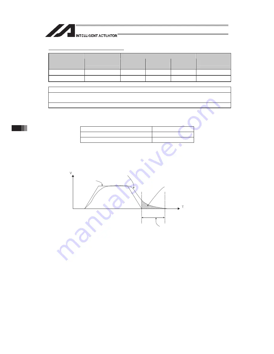
Feedback pulses
Command
pulses
If the set positioning width exceeds this area,
the settling time will become “0”.
Settling time
Summary of Contents for PSEL
Page 2: ......
Page 10: ......
Page 18: ...8 Part 1 Installation ...
Page 37: ...27 Part 1 Installation 2 2 axis specification with battery ...
Page 382: ...372 Appendix Micro cylinder RCL Series Current limiting value ratio Push force N ...
Page 476: ...466 Appendix ...
Page 480: ...470 ...
Page 485: ...475 ...
Page 487: ...INTELLIGENT ACTUATOR SEL Language Programming Manual Eighth Edition ...
Page 488: ......
Page 490: ......
Page 494: ......
Page 518: ...24 ...
Page 526: ...32 ...
Page 831: ... 11 Actuator Control Declaration 337 Example DFIF 1 170 ...
Page 1060: ......
Page 1061: ......


