


[1
1] Actuator
Control
Declaration
331
z
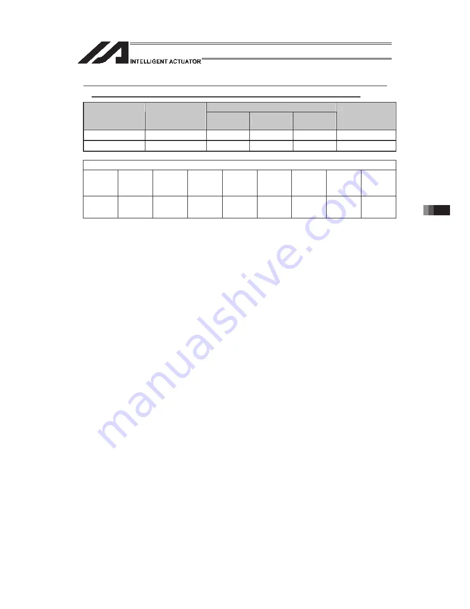
LEFT (Dedicated SCARA command/Change current arm system to left
arm (arm 2 operation involved if current arm system is opposite))
Command, declaration
Extension
condition
(LD, A, O, AB, OB)
Input condition
(I/O, flag)
Command,
declaration
Operand 1
Operand 2
Output
(Output, flag)
E
N, Cnd
Cmnd
Operand 1
Operand 2
Pst
Optional Optional
LEFT
Prohibited
Prohibited
PE
Applicable models
XSEL
-J/K
XSEL
-P/Q/
PCT/QCT
XSEL
-R/S
XSEL
-JX/KX
XSEL
-PX/QX
XSEL
-RX/SX/
RXD/SXD
ASEL
PSEL
SSEL
TT/TTA MSEL
u
u
u
{
{
{
u
u
{
(PCX/PGX
only)
[Function]
Change the current SCARA arm system to the left arm system. If the current arm
system is the right arm system, arm 2 is moved to change it to the left arm
system. After the operation, arms 1 and 2 form a straight line. No arm operation is
performed if the current arm system is the left arm system.
(Note 1)
To use a RIGH or LEFT command, the speed must be set with VELS even when
a SCARA PTP operation command is not used.
(Note 2)
In XSEL-RX/SX/RXD/SXD 8-axes Series, GRP and BASE Command are
available also in the actuator control declaration commands SLTL, SLWK, WGHT,
WGT2, PTPR, PTPL PTPE, PTPD, RIGH, LEFT and the system information
acquirement command GARM. Establish the setting to have all the SCARA axes
valid. Error No. C30 “Axis Pattern Error” will occur if even one axis is set invalid
by GRP and BASE Commands.
When GRP and BASE Commands are undeclared, all the axes are effective
(equivalent to GRP 11111111).
[Example 1]
GRP
1111
It makes the 1st to 4th axes effective
LEFT
The current arm system of the SCARA axes (1st to
4th axes) is changed to the right arm system.
[Example 2]
GRP
11111111
It makes the 1st to 8th axes effective.
LEFT
The current arm system of the SCARA axes (1st to
4th axes) and SCARA axes (5th to 8th axes) is
changed to the left arm system.
Summary of Contents for PSEL
Page 2: ......
Page 10: ......
Page 18: ...8 Part 1 Installation ...
Page 37: ...27 Part 1 Installation 2 2 axis specification with battery ...
Page 382: ...372 Appendix Micro cylinder RCL Series Current limiting value ratio Push force N ...
Page 476: ...466 Appendix ...
Page 480: ...470 ...
Page 485: ...475 ...
Page 487: ...INTELLIGENT ACTUATOR SEL Language Programming Manual Eighth Edition ...
Page 488: ......
Page 490: ......
Page 494: ......
Page 518: ...24 ...
Page 526: ...32 ...
Page 831: ... 11 Actuator Control Declaration 337 Example DFIF 1 170 ...
Page 1060: ......
Page 1061: ......


