


[12]
Actuator Control Command
363
z
PUSH (Move by push motion)
Command, declaration
Extension
condition
(LD, A, O, AB, OB)
Input condition
(I/O, flag)
Command,
declaration
Operand 1
Operand 2
Output
(Output, flag)
E
N, Cnd
Cmnd
Operand 1
Operand 2
Pst
Optional Optional
PUSH
Target position
number
Prohibited PE
Applicable models
All models [Refer to Section 5.1 for details of models]
{
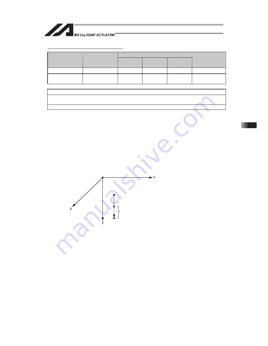
[Function]
Perform push-motion operation until the target position specified in operand 1 is
reached.
The axes move in a normal mode from the position origin to the push-motion
approach start position as determined by a PAPR command, after which
push-motion approach operation (toque-limiting operation) will be performed. The
speed of push-motion approach operation (toque-limiting operation) is determined
by the push-motion approach speed specified by a PAPR command. If the output
field is specified, the output will turn ON when a contact is confirmed, and turn
OFF when a missed contact is detected.
Movement from the position origin to start position of push-motion approach
conforms to the speed and acceleration/deceleration specified by VEL/ACC/DCL
commands or in the position data table.
The pressing force can be adjusted in Driver Card Parameter No. 38 Limitation
for pressing torque in positioning process (default value = 70%) or PTRQ
Command.
(Note 1)
A PUSH command only moves a single axis. If multiple axes are specified, an
“Error No. C91, Multiple push-axes specification error” will generate.
(Note 2)
A push-motion approach speed exceeding the maximum speed permitted by the
system will be clamped at the maximum speed.
(The maximum system speed is not the maximum practical speed. Determine a
practical speed by considering the impact upon contact, etc.)
Push-motion approach distance
Target position
Start position of push-motion approach operation (torque-limited operation)
Position origin
Summary of Contents for PSEL
Page 2: ......
Page 10: ......
Page 18: ...8 Part 1 Installation ...
Page 37: ...27 Part 1 Installation 2 2 axis specification with battery ...
Page 382: ...372 Appendix Micro cylinder RCL Series Current limiting value ratio Push force N ...
Page 476: ...466 Appendix ...
Page 480: ...470 ...
Page 485: ...475 ...
Page 487: ...INTELLIGENT ACTUATOR SEL Language Programming Manual Eighth Edition ...
Page 488: ......
Page 490: ......
Page 494: ......
Page 518: ...24 ...
Page 526: ...32 ...
Page 831: ... 11 Actuator Control Declaration 337 Example DFIF 1 170 ...
Page 1060: ......
Page 1061: ......


