


2. Connection with Host System
96
Output
Pin
No.
Wire
color
Port
No.
Standard
(factory-set) function
34 Yellow-4 300 Output
of
operation-cancellation
level or higher error (OFF)
No. 46
0: General-purpose output
1: Output of operation-cancellation level or higher error (ON)
2: Output of operation-cancellation level or higher error (OFF)
3: Output of operation-cancellation level or higher error + Emergency stop
output (ON)
4: Output of operation-cancellation level or higher error + Emergency stop
output (OFF)
5: Error output of cold start level or more (ON)
6: Error output of cold start level or more (OFF)
35 Green-4 301 READY
output
(PIO-trigger program
operation enabled AND no
cold-start level or higher
error) (Main application
Ver.0.20 or later)
No. 47
0: General-purpose output
1: READY output (PIO-trigger program operation enabled)
2: READY output (PIO-trigger program operation enabled AND no
operation-cancellation level or higher error)
3: READY output (PIO-trigger program operation enabled AND no cold-start
level or higher error)
36 Blue-4 302
Emergency
stop
output
(OFF)
No. 48
0: General-purpose output
2: Emergency stop output (ON)
3: Emergency stop output (OFF)
37
Purple-4 303 General-purpose output
No. 49
0: General-purpose output
1: AUTO mode output
2: Auto operation output (When other parameter No. 12 is set to ‘1’)
38
Gray-4
304 General-purpose output
No. 50
0: General-purpose output
1: Output at the time of “All Effective Axes Homing (=0)”
2: Output when all effective linear drive axis home-return operation is
complete (coordinate is established)
3: Output when all the effective axes home preset coordinates are set
* Use MOVP Command, not HOME Command, if moving the ABS encoder
axes to the coordinate 0 or home preset coordinate.
39
White-4 305 General-purpose output
No. 51
0: General-purpose output
1: Axis 1 in-position output (turned OFF when pressing missed)
2: Output during the Axis 1 servo ON
40
Black-4
306 General-purpose output
No. 52
0: General-purpose output
1: Axis 2 in-position output (turned OFF when pressing missed)
2: Output during the Axis 2 servo ON
41
Brown-5 307 General-purpose output
No. 53
0: General-purpose output
1: Axis 3 in-position output (turned OFF when pressing missed)
2: Output during the Axis 3 servo ON
42
Red-5
308 General-purpose output
No. 54
0: General-purpose output
1: Axis 4 in-position output (turned OFF when pressing missed)
2: Output during the Axis 4 servo ON
43
Orange-5
309 General-purpose output
No. 55
0: General-purpose output
1: Axis 5 in-position output (turned OFF when pressing missed)
2: Output during the Axis 5 servo ON
44
Yellow-5 310 General-purpose output
No. 56
0: General-purpose output
1: Axis 6 in-position output (turned OFF when pressing missed)
2: Output during the Axis 6 servo ON
45
Green-5 311 General-purpose output
No. 57
0: General-purpose output
1: Axis 7 in-position output (turned OFF when pressing missed)
2: Output during the Axis 7 servo ON (system monitoring task output)
46
Blue-5
312 General-purpose output
No. 58
0: General-purpose output
1: Axis 8 in-position output (turned OFF when pressing missed)
2: Output during the Axis 8 servo ON (system monitoring task output)
47
Purple-5 313 General-purpose output
No. 59
0: General-purpose output
1: System-memory backup battery voltage low alarm level or lower
48
Gray-5
314 General-purpose output
No. 60
0: General-purpose output
1: Absolute-battery backup battery voltage low alarm level or lower
(OR check of all axes. If an error level is detected, this output is retained
until power-ON reset or software reset.)
49
White-5 315 General-purpose output
No. 61
50 Black-5 0V
input
x
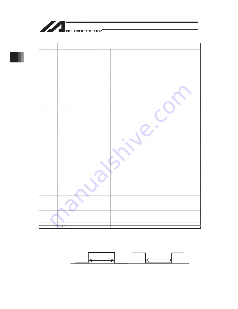
By default, the ON/OFF state of an input signal is recognized by the controller when the
signal has remained ON/OFF for approx. 4msec or more.
x
The setting for this ON/OFF duration can be changed using I/O parameter No. 20, “Input
filtering period”.
[2] Virtual I/O Port
Should be the same as XSEL-R/S. [Refer to 2.1.4 XSEL-R/S]
ON duration
OFF duration
Summary of Contents for PSEL
Page 2: ......
Page 10: ......
Page 18: ...8 Part 1 Installation ...
Page 37: ...27 Part 1 Installation 2 2 axis specification with battery ...
Page 382: ...372 Appendix Micro cylinder RCL Series Current limiting value ratio Push force N ...
Page 476: ...466 Appendix ...
Page 480: ...470 ...
Page 485: ...475 ...
Page 487: ...INTELLIGENT ACTUATOR SEL Language Programming Manual Eighth Edition ...
Page 488: ......
Page 490: ......
Page 494: ......
Page 518: ...24 ...
Page 526: ...32 ...
Page 831: ... 11 Actuator Control Declaration 337 Example DFIF 1 170 ...
Page 1060: ......
Page 1061: ......


