


[1
1]
Actuator Control Declaration
305
Ĺ
1-axis
2-axis
Ļ
4-axis
Ļ
Ĺ
1-axis
z
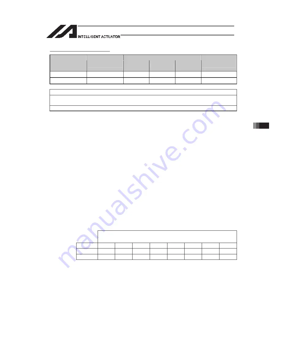
GRP (Set group axes)
Command, declaration
Extension
condition
(LD, A, O, AB, OB)
Input condition
(I/O, flag)
Command,
declaration
Operand 1
Operand 2
Output
(Output, flag)
E
N, Cnd
Cmnd
Operand 1
Operand 2
Pst
Optional Optional
GRP
Axis
pattern
Prohibited
CP
Applicable models
All models [Refer to Section 5.1 for details of models]
{
[Function]
Allow only the position data of the axis pattern specified in operand 1 to become
valid.
The program assumes that there are no data for other axes not specified.
When multiple programs are run simultaneously, assigning axes will allow the
same position data to be used effectively among the programs.
GRP Command is available in the operand axis pattern indication SEL
commands except for OFST, DFTL, DFWK, DFIF, GTTL, GTWK and GTIF or the
servo operation commands to use the position data, actuator control declaration
commands SLTL, SLWK, WGHT, WGT2, PTPR, PTPL, PTPE, PTPD, RIGH and
LEFT, and the system information acquirement command GARM.
GRP Command activates in the condition before the axis number changed due to
BASE Command.
(Note 1)
In XSEL-RX/SX/RXD/SXD, GRP and BASE Command are available also in the
actuator control declaration commands SLTL, SLWK, WGHT, WGT2, PTPR,
PTPL, PTPE, PTPD, RIGH, LEFT and the system information acquirement
command GARM. Establish the setting to have all the SCARA axes valid. Error
No. C30 “Axis Pattern Error” will occur if even one axis is set invalid by GRP and
BASE Commands.
[Example]
Express what axis is to be used by using either “1” or “0”.
(Superior) (Inferior)
Axis
No. 8-axis 7-axis
6-axis
5-axis
4-axis
3-axis 2-axis 1-axis
Use 1 1 0 1 1 1 1 1
Unused
0 0 1 0 0 0 0 0
Ɣ
When using 1
st
and 2
nd
axes;
000011… (0 in front are not necessary. Remove 0 and make it 11.)
Ɣ
When using 1
st
and 4
nd
axes;
1001… (In this case, 0 are necessary to express the position of the 4
th
axis.)
Summary of Contents for PSEL
Page 2: ......
Page 10: ......
Page 18: ...8 Part 1 Installation ...
Page 37: ...27 Part 1 Installation 2 2 axis specification with battery ...
Page 382: ...372 Appendix Micro cylinder RCL Series Current limiting value ratio Push force N ...
Page 476: ...466 Appendix ...
Page 480: ...470 ...
Page 485: ...475 ...
Page 487: ...INTELLIGENT ACTUATOR SEL Language Programming Manual Eighth Edition ...
Page 488: ......
Page 490: ......
Page 494: ......
Page 518: ...24 ...
Page 526: ...32 ...
Page 831: ... 11 Actuator Control Declaration 337 Example DFIF 1 170 ...
Page 1060: ......
Page 1061: ......


