


331
Part 3 Positioner Mode
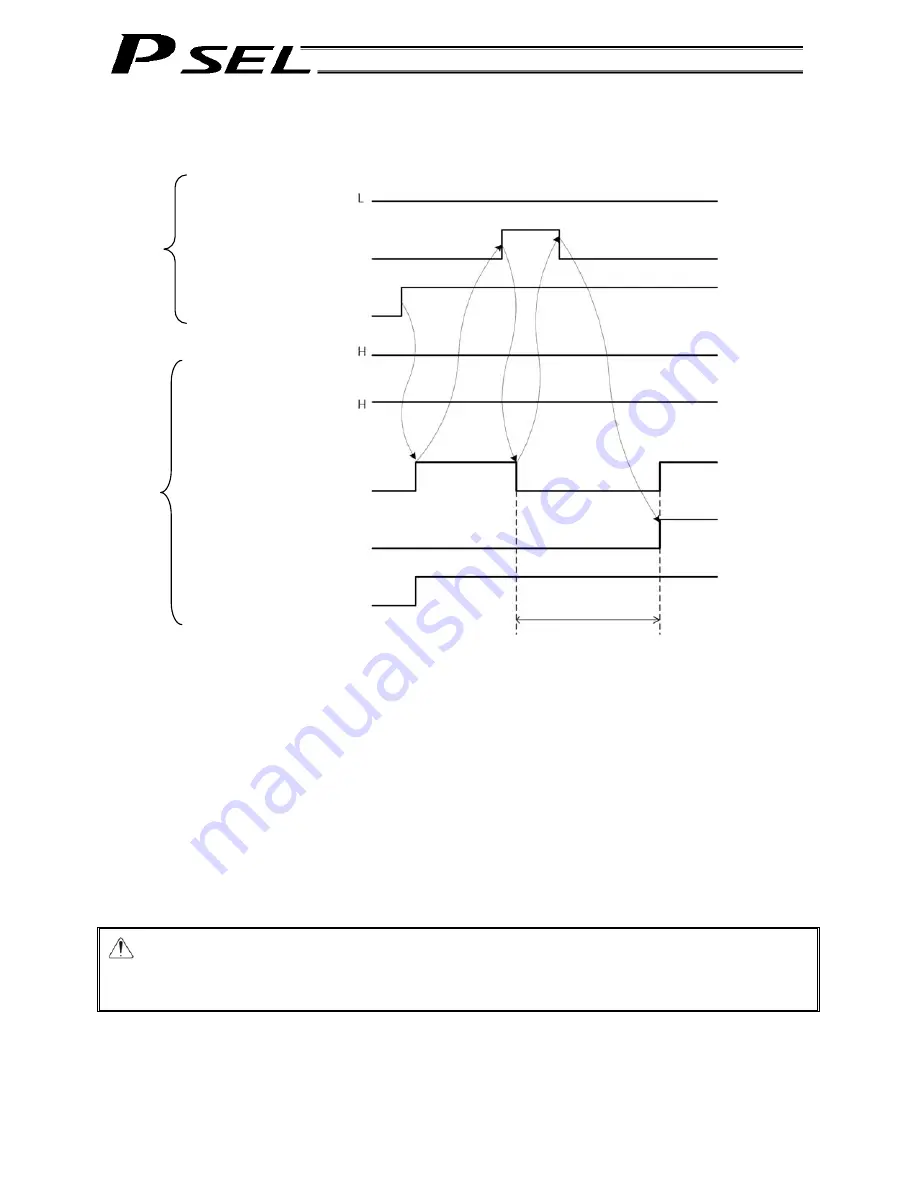
000: Start
(005)
001: Home return
(006)
002: Servo ON
(007)
300: Alarm
301: Ready
302: Positioning complete
(305)
303: Home return complete
(306)
304: Servo ON status
(307)
[3]
[2]
[4]
[5]
[6]
[1]
5.2 Home
Return
Timings associated with home-return operation are illustrated below. The figures in parentheses indicate
port numbers for axis 2.
Timing Chart of Home-return Operation (Standard Positioner Mode)
Perform home-return operation by following the procedure explained below.
* Before commencing the procedure, confirm that the ready output signal and alarm output signal are OFF.
[1] Turn ON the servo ON input signal.
[2] Confirm that the servo-ON status output signal is ON.
[3] Turn ON the home-return input signal.
[4] Confirm that the positioning complete output signal is OFF.
[5] Turn OFF the home-return input signal.
[6] Confirm that the home-return complete output signal is ON. Home return is now completed.
*Pause and *cancellation inputs are contact-B input signals (always ON), so keep these signals ON while home return
is in progress.
To initiate home return using the home-return signal input, the servo ON input signal must be ON. These operation
commands will not be accepted if the servo ON input signal is OFF. Note, however, that only the commands will be
ignored and no error will generate.
Warning: If the servo is turned on near the mechanical end, excited phase detection may not be
performed properly and an excited pole indetermination error or excited pole detection
error may generate.
Move the slider, rod, etc., away from the mechanical end before turning on the servo.
Home return in progress
Input
Output
Summary of Contents for PSEL
Page 2: ......
Page 10: ......
Page 18: ...8 Part 1 Installation ...
Page 37: ...27 Part 1 Installation 2 2 axis specification with battery ...
Page 382: ...372 Appendix Micro cylinder RCL Series Current limiting value ratio Push force N ...
Page 476: ...466 Appendix ...
Page 480: ...470 ...
Page 485: ...475 ...
Page 487: ...INTELLIGENT ACTUATOR SEL Language Programming Manual Eighth Edition ...
Page 488: ......
Page 490: ......
Page 494: ......
Page 518: ...24 ...
Page 526: ...32 ...
Page 831: ... 11 Actuator Control Declaration 337 Example DFIF 1 170 ...
Page 1060: ......
Page 1061: ......


