


1. Preparation in
Advance
40
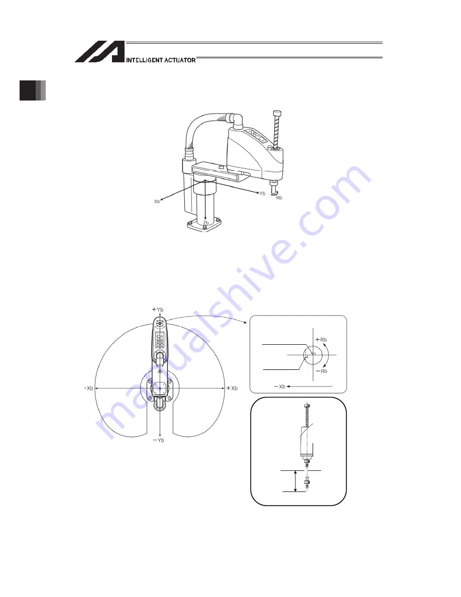
(1) Base coordinate system (= Work Coordinate System No. 0)
This is a combination of three-dimensional rectangular coordinates and rotational axis
coordinates defined in the robot prior to shipment.
Work Coordinate System No. 0 (= 0 work coordinate system offsets) = Base coordinate
system.
* There is no rotary axis on Three-Axis Type SCARA ROBOT (IXP-3N****). (Xb, Yb and Zb)
are available to indicate as the target position.
The XY-axis home is the center of the base (center of rotation of arm 1).
The Z-axis home is the top edge of the effective Z-axis stroke.
The R-axis home is where the D-cut surface faces the -Xb direction.
The X-axis, Y-axis, Z-axis and R-axis on the base coordinate system are indicated as Xb, Yb,
Zb and Rb, respectively.
Zb=0
-Zb
㸩
Zb
Stroke
Z-axis position
R-axis position as viewed
from above
Center of tool
installation surface
D-cut surface
of R-axis
Summary of Contents for PSEL
Page 2: ......
Page 10: ......
Page 18: ...8 Part 1 Installation ...
Page 37: ...27 Part 1 Installation 2 2 axis specification with battery ...
Page 382: ...372 Appendix Micro cylinder RCL Series Current limiting value ratio Push force N ...
Page 476: ...466 Appendix ...
Page 480: ...470 ...
Page 485: ...475 ...
Page 487: ...INTELLIGENT ACTUATOR SEL Language Programming Manual Eighth Edition ...
Page 488: ......
Page 490: ......
Page 494: ......
Page 518: ...24 ...
Page 526: ...32 ...
Page 831: ... 11 Actuator Control Declaration 337 Example DFIF 1 170 ...
Page 1060: ......
Page 1061: ......


