GK600 User Manual
Chapter 3 Installation and Wiring
- 27 -
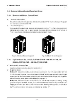
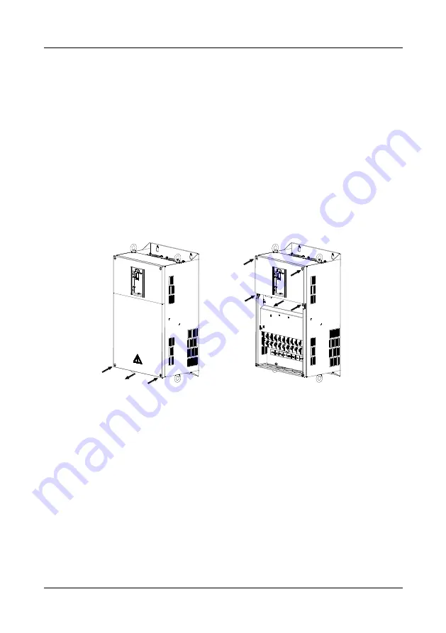
3.3.3 Open & Mount the Covers of GK600-2T11(B) and above,
GK600-4T18.5G/22L(B) and above
Remove the control panel
Use the remove method as stated in Section 3.3.1.
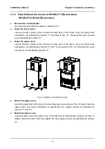
Open the lower cover
Loosen the two captive cover screws at lower part of the lower cover by using cross
screwdriver, as indicated by number "1" as shown in Fig. 3-7, then pull the cover out and
up as indicated by number "2".
Open the upper cover
Loosen the two captive cover screws at lower part of the lower cover by using cross
screwdriver, as indicated by number "3" and “4” as shown in Fig. 3-7, then pull the cover
out and up as indicated by number "5".
Fig. 3-7 Open & mount the covers
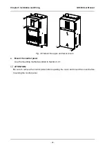
Mount the upper cover
Insert the upper part of the cover into mounting groove as shown in Fig. 3-8 (left), close the
upper cover, use cross screwdriver to tighten the four captive screws, as indicated by
number “1” and "2".
Mount the lower cover
Insert the lower cover into upper cover in the direction as indicated by number 3 in Fig. 3-8
(right), close the lower cover and tighten the two captive screws, as indicated by number
"4".
1
1
2
3
4
4
5
3

