Chapter 6 Specification of Parameters GK600 User Manual
- 180 -
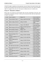
d0-25
Temperature transducer signal
input of motor 1
Range: 0~2
Factory default: 1
0: AI1
1: AI2
2: EAI
When d0-23 is set to "2: judged by temperature transducer ", the analog signal input of
temperature sensor of motor 1 is set by this parameter. The drive compares the signal input
value via this analog channel with the thermal protection threshold set by d0-26. If it is bigger
than the threshold, the drive will immediately give an alarm of motor overheat fault "oH2".
Protection through temperature sensor has no characteristic of inverse time lag curve.
d0-26
Thermal protection threshold of
motor 1 temperature transducer
Range: 0.00V~10.00V
Factory default:
10.00V
This parameter works together with d0-25, and this parameter value, corresponding to motor 1
overheat protection point, needs to be calculated in accordance with the type of temperature
sensor. Please consult GTAKE technical service engineer for this parameter value setting.
When the input analog signal through the channel selected by d0-25 is bigger than this
threshold, the drive will immediately trip with motor overeat fault "oH2".
Group d1 V/f Control Parameters of Motor 1
Set control parameters in Group d1 when motor 1 is selected as current load motor on which
V/f control is performed.
d1-00
V/f curve setting
Range: 0~8
Factory default: 0
Set the relation between output voltage and output frequency of the drive when motor 1 is
under V/f control.
0: Linear V/f
Applies to general constant-torque load. When drive output frequency is 0, output voltage will
be 0, while when output frequency is rated frequency of motor, the output voltage would be
rated voltage of motor.
1: Broken line V/f (determined by d1-01~d1-08)
Applies to spin drier, centrifuge, industrial washing machine and other special loads. When
drive output frequency is 0, output voltage will be 0, while when output frequency is rated
frequency of motor, the output voltage would be rated voltage of motor. What is different is
this pattern can set 4 inflection points by d1-01~d1-08. See Fig. 6-41.

