Chapter 6 Specification of Parameters GK600 User Manual
- 186 -
but the response will be slower. This parameter is applicable to loads such as fan and pump or
light-load for a long time. Where rapid change is required, this parameter is suggested to be
default set 0.0%.
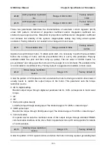
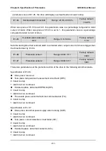
d1-16
V/f oscillation suppression
gain 1
Range: 0~3000
Factory default:
38
d1-17
V/f oscillation suppression
gain 2
Range: 0~3000
Factory default: 0
Under V/f control, speed and current oscillation is likely to occur due to load vibration, and may
lead to system failure even over current protection. This is particularly obvious during no-load
or light-load applications. The appropriate setting of parameter values of d1-16 and d1-17
would effectively suppress speed and current oscillation. In many case it is not necessary to
modify the default setting. Please make progressive change around default setting, since
excessive setting will influence V/f control performance.
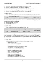
d1-18
Voltage setting on V/f
separated pattern
Range: 0~5
Factory default: 0
This parameter takes effect when d1-00 is set to 7 or 8.
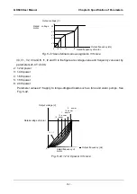
0: d1-19 digital setting
Under V/f separated pattern 1, drive output voltage is completely determined by d1-19. 100%
corresponds to motor rated voltage.
Under V/f separated pattern 2, output voltage = voltage calculated according to linear V/f
curve x 2 x d1-19.
1: Set by AI1
2: Set by AI2
3: Set by EAI
Under V/f separated pattern 1, drive output voltage is completely determined by the selected
analog. The biggest setting is the motor rated voltage.
Under V/f separated pattern 2, output voltage = voltage calculated according to linear V/f
curve x the proportion determined by the analog input. The maximum set value can be
200%.
4: Process PID output
Outputs voltage on the basis of process PID.
Under V/f separated pattern 1, output voltage is determined by the output of process PID.
Under V/f separated pattern 2, the output of process PID is a proportional value whose
maximum set value could be 200%. Then this proportional value is multiplied by the voltage
calculated according to linear V/f curve to obtain drive output voltage. Refer to parameter
group F0 for information of process PID.
5: AI1 + process PID output
Under V/f separated pattern 1, drive output voltage is determined by "AI1 + process PID

