GK600 User Manual
Chapter 6 Specification of Parameters
-
195 -
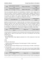
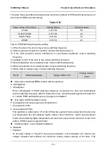
The table below specifies the setting range and factory default of PWM switching frequency of
the drives at different power ratings:
Table 6-16
Power rating of the drives
Setting Range
Factory Default
≤15kW
0.7k~16k
8k
18.5kW~45kW
0.7k~10k
4k
55kW~75kW
0.7k~8k
3k
≥90kW
0.7k~3k
2k
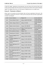
Tips for PWM switching frequency setting:
1) When the motor line is too long, reduce switching frequency.
2) When torque at low speed is unstable, reduce switching frequency.
3) If the drive produces severe interference to surrounding equipment, reduce switching
frequency.
4) Leakage current of the drive is big, reduce switching frequency.
5) Drive temperature rise is relatively high, reduce switching frequency.
6) Motor temperature rise is relatively high, increase switching frequency.
7) Motor noise is relatively big, increase switching frequency.
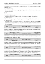
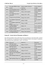
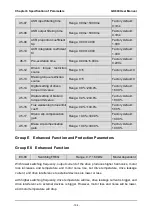
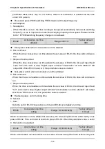
E0-01
PWM optimization
Range: 0000~1121
Factory default:
0100
Ones place: switching FREQ relation with temperature
0: Self-adaption
1: No adaption
When self-adaption of PWM switching frequency is selected, the drive will automatically
reduce switching frequency with the temperature rise, protecting itself against overheat. Set
to 1 where PWM switching frequency change is not allowed.
Tens place: PWM modulation mode
0: five-segment and seven-segment self-switchover
1: five-segment mode
2: seven-segment mode
This selection is valid only for V/f control. When five-segment mode is selected, the drive has
low temperature rise but relatively higher output current harmonic. Under seven-segment
mode, it has relatively higher temperature rise but lower output current harmonic. Under SVC
pattern, PWM is seven-segment mode.
Hundreds place: over-modulation adaption
0: Disabled
1: Enabled
At low grid voltage or long-term heavy-duty operation, over-modulation can improve the
voltage utilization and enhance the maximum voltage output capacity of the drive. This

