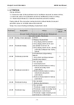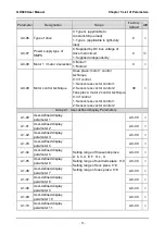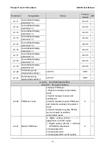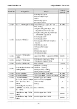
Chapter 4 Operation and Run Instructions GK600 User Manual
- 66 -
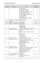
10) Press
for five times to change "0" to "5";
11) Press
to save the value (50.00) of b0-09. Then the control panel will
automatically switch to display the next function code (b0-10);
12) Press
to exit parameter edit status.
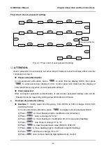
Flow chart is shown below:
Fig. 4-12 Flow chart of upper limit frequency modification
Example 2
: user parameter initialization
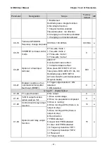
1) In non-parameter edit status, press
to display current parameter A0-00;
2) Press
three times to change "0" in the rightmost bit of A0-00 to "3";
3) Press
to display parameter value 0 of A0-03;
4) Press
once to change "0" to "2" or "3" ("2" motor parameter excluded, "3"
means motor parameter included);
5) Press
to save the value of A0-03.Then control panel will automatically display
parameter A0-00;
6) Press
to escape parameter edit status.
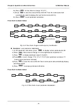
Flow chart is shown below:
Fig. 4-13 Flow chart of user parameter initialization
放弃修改
50.00
ENT
A0-00
A
0-00
>>
b
0-00
▲
>>
b0-0
0
b0-0
9
600.00
6
00.00
0
00.00
0
0
0.00
050.00
b0-09
b0-10
50.00
▲
ENT
>>
▼
>>
▲
ESC
ENT
ESC
50.00
ENT
A0-0
0
A0-0
3
0
2
或
3
A0-00
50.00
▲
ENT
▲
ENT
ESC
Escape modification
2 or 3

