GK600 User Manual
Chapter 3 Installation and Wiring
- 25 -
3.3 Remove & Mount Control Panel and Cover
3.3.1 Remove and Mount Control Panel
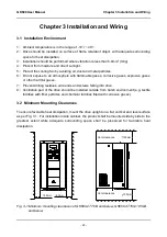
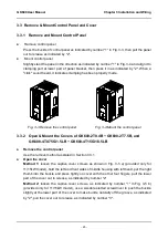
Remove control panel
Press the buckle of control panel as indicated by number "1" in Fig. 3-3, then pull the panel
out to release as indicated by "2".
Mount control panel
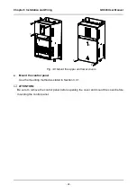
Slightly slant the panel in the direction as indicated by number "1" in Fig. 3-4 and align it to
clamping port at lower part of panel bracket, then press it in as indicated by "2". When a
"click" sound heard, it indicates clamping has been properly made.
Fig. 3-3 Remove the control panel Fig. 3-4 Mount the control panel
3.3.2 Open & Mount the Covers of GK600-2T0.4B ~ GK600-2T7.5B, and
GK600-4T0.75G/1.5LB
~ GK600-4T15G/18.5LB
Remove the control panel
Use the remove method as stated in Section 3.3.1.
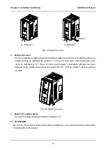
Open the cover
Method 1:
loosen the captive cover screws as shown in Fig. 3-5 a) (provided only for
11/15kW model), hold the left and front sides of middle housing with left hand, put the right
thumb into the buckle and press tightly on cover with the other four fingers, pull the lower
part of the cover out to release, as indicated by number "2".
Method 2:
loosen the captive cover screws, as indicated by number "1" in Fig. 3-5 b)
(provided only for 11/15kW model), use a sizeable slotted screwdriver to push the buckle
slightly at the lower part of the cover to make buckle naturally off the groove, as indicated
by "2", pull the cover out to release, as indicated by number "3".
1
2
1
2

