Chapter 6 Specification of Parameters
GK600 User Manual
- 230 -
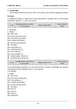
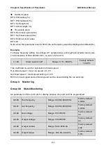
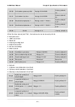
Hundreds place
BIT0: PID setting (%)
BIT1: PID feedback (%)
BIT2: Set length (m)
BIT3: Actual length (m)
Thousands place
BIT0: Run linear speed (m/s)
BIT1: Set linear speed (m/s)
BIT2: External count value
BIT3: DI
Note: when this parameter is set to 0000, the set frequency would be displayed as default (Hz).
Example:
To display frequency setting, bus voltage, AI1 sampled value, set length and external count value,
L1-02 should be: 0100 0100 0001 0011, i.e. set L1-02 to 4413.
L1-03
Linear speed coeff
Range: 0.1%~999.9%
Factory default:
100.0%
This coefficient is used for calculation of linear speed.
Run linear speed = motor run speed x L1-03
Set linear speed = motor speed setting x L1-03
Both run linear speed and set linear speed can be viewed during the run and stop.
Group U Monitoring
Group U0 Status Monitoring
All parameters of Group U0 are for display purpose only and can‟t be programmed.
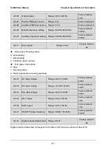
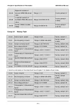
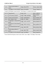
U0-00 Run frequency
Range: 0.00Hz~600.00Hz
Factory default:
0.00Hz
U0-01 Set frequency
Range: 0.00Hz~600.00Hz
Factory default:
0.00Hz
U0-02 Bus voltage
Range: 0V~65535V
Factory default:
0V
U0-03 Output voltage
Range: 0V~65535V
Factory default:
0V
U0-04 Output current
Range: 0.0A~6553.5A
Factory default:
0.0A
U0-05 Output torque
Range: -300.0%~300.0%
Factory default:
0.0%

