Chapter 6 Specification of Parameters GK600 User Manual
- 128 -
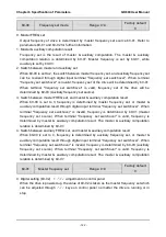
10: Communication
Upper computer is the auxiliary frequency set source of the drive through standard RS485
communication interface on the drive. Refer to Group H0 and appendix on this manual for
further information about communication protocol, and programming, etc.
ATTENTION:
Auxiliary frequency setting can be forcibly switched to b0-04 via terminal "auxiliary
frequency setting switched to digital setting b0-04". When this terminal is disabled, master
frequency setting is determined by b0-03. When terminal is enabled, master frequency
setting shall be the value of b0-04.
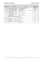
b0-04
Auxiliary FREQ digital
setting
Range: lower limit frequency ~
upper limit frequency
Factory default:
0.00Hz
When auxiliary frequency command is set to either 1 or 2, this parameter value should be the
initial value of auxiliary frequency command.
b0-05
Auxiliary FREQ range
Range: 0~1
Factory default: 0
0: Relative to maximum frequency
1: Relative to master frequency
See b0-06 specification for details.
b0-06
Auxiliary FREQ coeff
Range: 0.0%~100.0%
Factory default:
100.0%
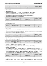
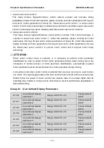
When b0-03 selects AI1, AI2, EAI, X6/DI pulse input, or process PID output as auxiliary
frequency command sources, b0-05 and b0-06 will determine the final output value of auxiliary
frequency command.
When b0-05 is set to 0 (relative to maximum frequency): When AI1, AI2, EAI, X6/DI pulse input
is selected for auxiliary frequency command, the frequency that corresponds to maximum
value of the source should be (b0-08×b0-06).
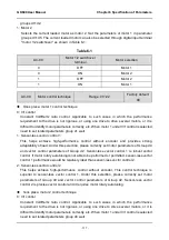
Example:
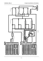
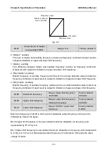
Select AI1 as auxiliary frequency command source (set b0-03 to 3) and set AI1 to curve 1
(Ones place of C2-00 is 0) as shown in Fig. 6-5. In such a case, the frequency that corresponds
to the maximum input of curve 1 should be: (C2-02) × [(b0-08) × (b0-06)].

