Functions
6-73
7SA6 Manual
C53000-G1176-C156-2
short-circuits will result in the fast cancellation of the power swing block in the affected
phases, thereby allowing the tripping of the Distance Protection.
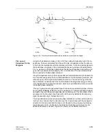
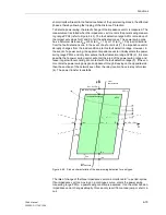
To detect a power swing, the rate of change of the impedance vector is measured. The
measurement is started when the impedance vector enters the power swing measur-
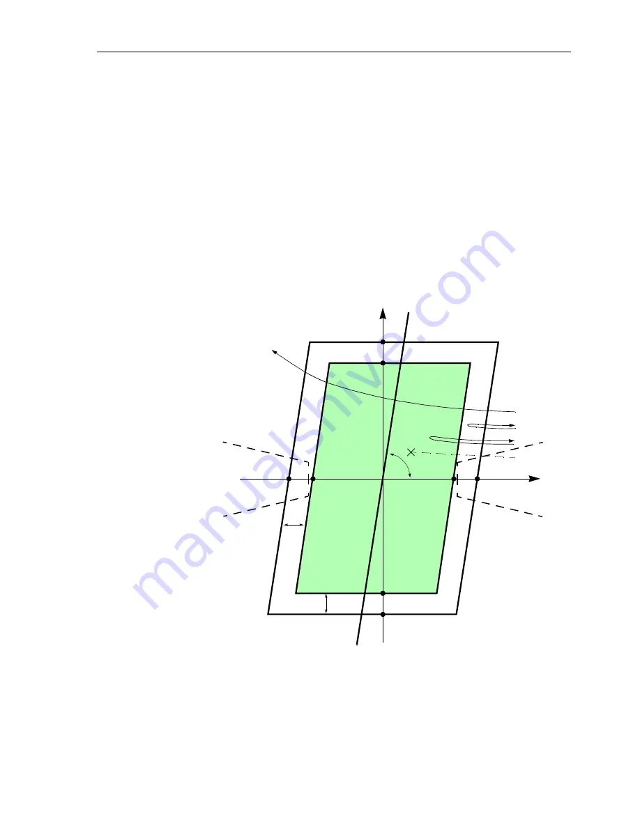
ing range PPOL (refer to Figure 6-40). The fault detection range APOL is made up of
the largest set values for R and X of all the activated zones. The power swing zone
has a minimum distance Z
diff
of 5
Ω
(at I
N
= 1 A) or 1
Ω
(at I
N
= 5 A) in all directions
from the fault detection zone. In the event of a short-circuit (1), the impedance vector
abruptly changes from the load condition into this fault detection range. However, in
the event of a power swing, the apparent impedance vector initially enters the power
swing range PPOL and only later enters the fault detection range APOL (2). It is also
possible that a power swing vector will enter the area of the power swing range and
leave it again without coming into contact with the fault detection range (3). If the vec-
tor enters the power swing polygon and passes through it leaving on the opposite side,
then the sections of the network seen from the relay location have lost synchronism
(4): The power transfer is unstable.
Figure 6-40
Pick up characteristic of the power swing detection for a polygon.
The rate of change of the three impedance vectors is monitored in
1
/
4
–period–cycles.
If an impedance vectors, moving on a continuous curve, enters the power swing
measuring range PPOL, a power swing condition is assumed. If on the other hand an
impedance vector changes abruptly, this can only result from a load jump or short cir-
cuit.
jX
R
(1)
(3)
(2)
(4)
Z
Diff
R
A
–R
P
–R
A
–X
P
–X
A
X
A
X
P
= X
A
+ Z
Diff
APOL
Z
Diff
R
P
= R
A
+ Z
Diff
ϕ
line
PPOL
power swing range
fault detection range
Line-
characteristic
Line-
characteristic
Содержание siprotec 7SA6
Страница 2: ...Siemens Aktiengesellschaft Book No C53000 G1176 C156 2 ...
Страница 18: ...xviii 7SA6 Manual C53000 G1176 C156 2 ...
Страница 32: ...Introduction 1 14 7SA6 Manual C53000 G1176 C156 2 ...
Страница 82: ...Hardware and Connections 2 50 7SA6 Manual C53000 G1176 C156 2 ...
Страница 119: ...SIPROTEC 4 Devices 4 25 7SA6 Manual C53000 G1176 C156 2 Figure 4 20 CFC Logic example ...
Страница 190: ...Configuration 5 62 7SA6 Manual C53000 G1176 C156 2 ...
Страница 559: ...Control During Operation 7 45 7SA6 Manual C53000 G1176 C156 2 Figure 7 45 Circuit breaker trip test in DIGSI 4 ...
Страница 652: ...Installation and Commissioning 8 78 7SA6 Manual C53000 G1176 C156 2 ...
Страница 724: ...Technical Data 10 56 7SA6 Manual C53000 G1176 C156 ...
Страница 800: ...Appendix A 76 7SA6 Manual C53000 G1176 C156 2 ...
Страница 866: ...Appendix B 66 7SA6 Manual C53000 G1176 C156 2 ...

