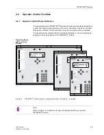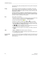
Initial Inspections
3-3
7SA6 Manual
C53000-G1176-C156-2
3.2
Inspections upon Receipt
3.2.1
Inspection of Features and Ratings
Ordering Number
Verify that the 7SA6 has the expected features by checking the complete ordering
number with the ordering number codes given in Sub-section A.1 of the Appendix.
Also check that the required and expected accessories are included with the device.
The ordering number of the device is on the nameplate sticker attached to the outside
of the housing. The nameplate also indicates the current, voltage, and power supply
ratings of the device. A verification that these ratings are the expected values is espe-
cially important. The jumpers for the control voltage of the binary inputs are set at the
factory for a DC control voltage equal to the DC voltage rating of the power supply.
The jumpers can be changed if a different control voltage is to be used.
3.2.2
Electrical Check
Operating conditions that meet VDE 0100/5.73 and VDE 0105 Part 1/7.83, or national
and international standards, are to be observed.
Before applying power supply voltage or any measuring quantities for the first time, be
sure the device has been in the operating area for at least two hours. This time period
allows the device to attain temperature equilibrium, and prevents dampness and con-
densation from occurring.
Power-Up
For a first electrical inspection of the device it is sufficient to ensure safe grounding of
the housing and to apply the power supply voltage:
o
Connect the ground of the device solidly to the ground of the location. The ground of
a 7SA6 designed for flush mounting is on the rear panel; the ground of a device de-
signed for surface mounting is on the terminal with the grounding symbol.
o
Prepare the connections to the power supply. Verify that the power supply voltage has
the correct magnitude. Check polarity connections to the device inputs. Follow the ap-
propriate connection diagram in the Appendix, Section A.2.
o
Close the protective switches to apply the power supply.
o
The green “RUN” LED on the front panel must light after no more than 0.5 second, and
the red “ERROR” LED must go out after no more than 10 seconds.
o
After no more than 15 seconds, the start-up messages must vanish from the display
(in which the complete ordering number, the version of firmware implemented, and the
factory number are shown), and the default display must appear. Depending on the
assignment of the LEDs, some indicators may light up during and after power-up.
Warning!
The following inspection steps are done in the presence of dangerous voltages. Only
appropriately qualified personnel familiar with and adhering to safety requirements
and precautionary measures shall perform these steps.
Содержание siprotec 7SA6
Страница 2: ...Siemens Aktiengesellschaft Book No C53000 G1176 C156 2 ...
Страница 18: ...xviii 7SA6 Manual C53000 G1176 C156 2 ...
Страница 32: ...Introduction 1 14 7SA6 Manual C53000 G1176 C156 2 ...
Страница 82: ...Hardware and Connections 2 50 7SA6 Manual C53000 G1176 C156 2 ...
Страница 119: ...SIPROTEC 4 Devices 4 25 7SA6 Manual C53000 G1176 C156 2 Figure 4 20 CFC Logic example ...
Страница 190: ...Configuration 5 62 7SA6 Manual C53000 G1176 C156 2 ...
Страница 559: ...Control During Operation 7 45 7SA6 Manual C53000 G1176 C156 2 Figure 7 45 Circuit breaker trip test in DIGSI 4 ...
Страница 652: ...Installation and Commissioning 8 78 7SA6 Manual C53000 G1176 C156 2 ...
Страница 724: ...Technical Data 10 56 7SA6 Manual C53000 G1176 C156 ...
Страница 800: ...Appendix A 76 7SA6 Manual C53000 G1176 C156 2 ...
Страница 866: ...Appendix B 66 7SA6 Manual C53000 G1176 C156 2 ...

