Functions
6-103
7SA6 Manual
C53000-G1176-C156-2
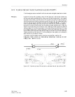
For all zones except Z1B, tripping results without release from the opposite line end,
allowing the protection to function with the usual grading characteristic independent of
the signal transmission.
Sequence
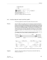
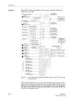
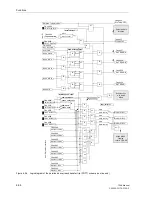
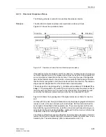
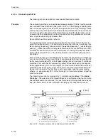
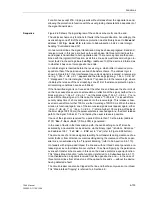
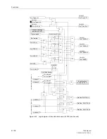
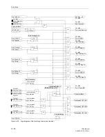
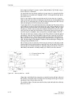
Figure 6-60 shows the logic diagram of the unblock scheme for one line end.
The unblock scheme only functions for faults in the forward direction. Accordingly, the
overreaching zone Z1B of the distance protection must definitely be set to
Forward
:
address
1351
Op. mode Z1B
, refer also to Subsubsection 6.2.4.2 under margin
heading “Controlled Zone Z1B”.
On two terminal lines, the signal transmission may be phase segregated. Send and
receive circuits in this case are built up for each phase. On three terminal lines the
send signal is transmitted to both opposite ends. The receive signals are then com-
bined with the logical AND function, as all three line ends must transmit during an in-
ternal fault. Via the setting
Line Config.
(address
2102
) the device is informed as
to whether it has one or two opposite line ends.
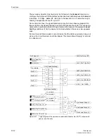
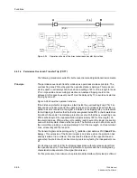
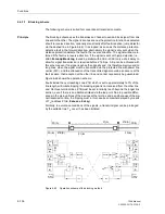
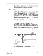
An unblock logic is inserted before the receive logic, which latter in essence corre-
sponds to that of the permissive overreach transfer scheme. The unblock logic is
shown in Figure 6-61. If an interference free unblock signal is received, a receive sig-
nal e.g. “
>Dis.T.UB ub 1
”, appears and the blocking signal e.g. “
>Dis.T.UB bl
1
” disappears. The internal signal “Unblock 1” is passed on to the receive logic, where
it initiates the release of the overreaching zone Z1B of the distance protection (when
all remaining conditions have been fulfilled).
If the transmitted signal is not received at the other line end because the short-circuit
on the line causes too severe an attenuation or reflection of the signal, neither the un-
block signal e.g. “
>Dis.T.UB ub 1
”, nor the block signal “
>Dis.T.UB bl 1
” is re-
ceived at the receiving end. In this case, the release ““>Unblock 1” is issued after a
security delay time of 20 ms and passed onto the receive logic. This release is how-
ever removed after a further 100 ms via the timer stage 100/100 ms. When the trans-
mission is functional again, one of the two receive signals must appear again, either
“
>Dis.T.UB ub 1
” or “
>Dis.T.UB bl 1
”; after a further 100 ms (drop-off delay of
the timer stage 100/100 ms) the quiescent state is reached again i.e. the direct release
path to the signal “Unblock L1” and thereby the usual release is possible.
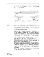
If none of the signals is received for a period of more than 10 s the alarm (address
2107) “
Dis.T.Carr.Fail
” (F.No. 4055) is generated.
In the case of faults in the transmission path, the overreaching zone Z1B can be
activated by an automatic reclose device, via the binary input “
>Enable ARzones
”
and address
1357
“
1st AR -> Z1B
” set to “Yes” (refer to Figure 6-38 bottom).
The occurrence of erroneous signals resulting from transients during clearance of ex-
ternal faults or from direction reversal resulting during the clearance of faults on par-
allel lines, is neutralized by the “Transient Blocking” (refer to Sub-section 6.6.1.10).
On feeders with single-sided infeed, the line end with no infeed cannot generate a re-
lease signal, as no fault detection occurs there. To achieve tripping by the permissive
overreach transfer scheme even in this case, the device contains a special function.
This “Weak Infeed Function” (echo function) is referred to in Subsubsection 6.6.1.11.
It is activated when a signal is received from the opposite line end — in the case of
three terminal lines from at least one of the opposite line ends — without the device
having detected a fault.
The circuit breaker can also be tripped at the line end that has only weak or no infeed.
This “Weak-Infeed Tripping” is referred to in Section 6.9.
Содержание siprotec 7SA6
Страница 2: ...Siemens Aktiengesellschaft Book No C53000 G1176 C156 2 ...
Страница 18: ...xviii 7SA6 Manual C53000 G1176 C156 2 ...
Страница 32: ...Introduction 1 14 7SA6 Manual C53000 G1176 C156 2 ...
Страница 82: ...Hardware and Connections 2 50 7SA6 Manual C53000 G1176 C156 2 ...
Страница 119: ...SIPROTEC 4 Devices 4 25 7SA6 Manual C53000 G1176 C156 2 Figure 4 20 CFC Logic example ...
Страница 190: ...Configuration 5 62 7SA6 Manual C53000 G1176 C156 2 ...
Страница 559: ...Control During Operation 7 45 7SA6 Manual C53000 G1176 C156 2 Figure 7 45 Circuit breaker trip test in DIGSI 4 ...
Страница 652: ...Installation and Commissioning 8 78 7SA6 Manual C53000 G1176 C156 2 ...
Страница 724: ...Technical Data 10 56 7SA6 Manual C53000 G1176 C156 ...
Страница 800: ...Appendix A 76 7SA6 Manual C53000 G1176 C156 2 ...
Страница 866: ...Appendix B 66 7SA6 Manual C53000 G1176 C156 2 ...

