


Installation and Commissioning
8-35
7SA6 Manual
C53000-G1176-C156-2
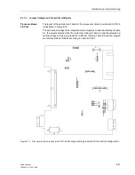
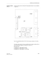
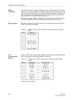
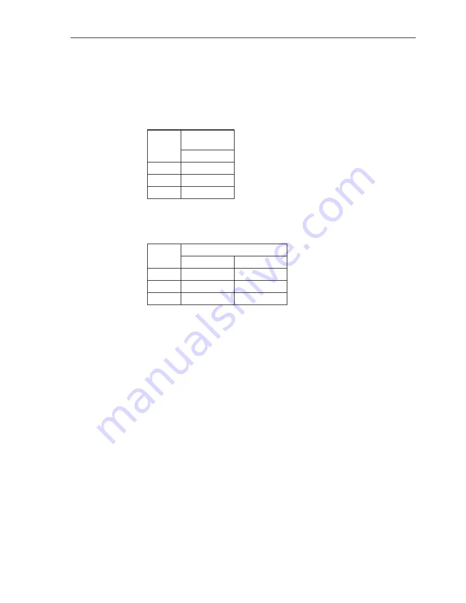
Jumpers X71, X72 and X73 on the input/output board C–I/O–2 are for setting the bus
address and must not be changed. Table 8-20 and 8-21 lists the jumper presettings.
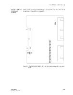
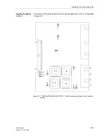
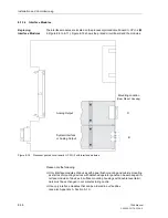
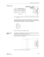
The mounting locations are shown in Figures 8-9 to 8-11.
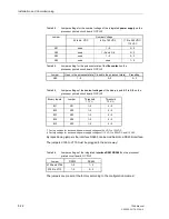
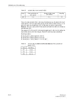
Table 8-20
Jumper setting of printed circuit board addresses of the binary input/output
boards B– I/O–2 for housing size
1
/
2
Jumper
Mounting
location
Slot 19
X71
1–2
X72
2–3
X73
1–2
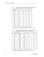
Tabelle 8-21 Jumper setting of printed circuit board addresses of the binary input/output
boards B– I/O–2 for housing size
1
/
1
Jumper
Mounting location
Slot 19 right
Slot 33 left
X71
1–2
2–3
X72
2–3
1–2
X73
1–2
1–2
Содержание siprotec 7SA6
Страница 2: ...Siemens Aktiengesellschaft Book No C53000 G1176 C156 2 ...
Страница 18: ...xviii 7SA6 Manual C53000 G1176 C156 2 ...
Страница 32: ...Introduction 1 14 7SA6 Manual C53000 G1176 C156 2 ...
Страница 82: ...Hardware and Connections 2 50 7SA6 Manual C53000 G1176 C156 2 ...
Страница 119: ...SIPROTEC 4 Devices 4 25 7SA6 Manual C53000 G1176 C156 2 Figure 4 20 CFC Logic example ...
Страница 190: ...Configuration 5 62 7SA6 Manual C53000 G1176 C156 2 ...
Страница 559: ...Control During Operation 7 45 7SA6 Manual C53000 G1176 C156 2 Figure 7 45 Circuit breaker trip test in DIGSI 4 ...
Страница 652: ...Installation and Commissioning 8 78 7SA6 Manual C53000 G1176 C156 2 ...
Страница 724: ...Technical Data 10 56 7SA6 Manual C53000 G1176 C156 ...
Страница 800: ...Appendix A 76 7SA6 Manual C53000 G1176 C156 2 ...
Страница 866: ...Appendix B 66 7SA6 Manual C53000 G1176 C156 2 ...