Hardware and Connections
2-14
7SA6 Manual
C53000-G1176-C156-2
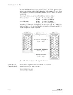
noted that all screws on the terminal module must be screws in before snapping the
cover on. The terminal covering cap can simply be removed with a screw driver 6x1.
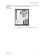
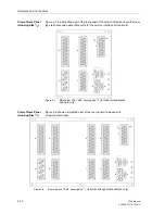
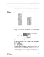
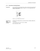
There are two types of covering caps, as shown in Figure 2-13. Ordering information
is provided in Section A.1 in the Appendix.
Figure 2-13
Covering caps for terminal blocks with screw terminals
Covering cap for
18 terminal voltage
Covering cap for
12 terminal voltage
connection terminal block
or 8 Terminal Current
connection terminal block
SI
EME
N
S
C
7333
4-
A
1
-C
31
-1
>PC
G
F<
:A
M
P
SI
EME
N
S
C
7333
4-
A
1
-C
32
-1
>PC
G
F
<
:A
M
P
Содержание siprotec 7SA6
Страница 2: ...Siemens Aktiengesellschaft Book No C53000 G1176 C156 2 ...
Страница 18: ...xviii 7SA6 Manual C53000 G1176 C156 2 ...
Страница 32: ...Introduction 1 14 7SA6 Manual C53000 G1176 C156 2 ...
Страница 82: ...Hardware and Connections 2 50 7SA6 Manual C53000 G1176 C156 2 ...
Страница 119: ...SIPROTEC 4 Devices 4 25 7SA6 Manual C53000 G1176 C156 2 Figure 4 20 CFC Logic example ...
Страница 190: ...Configuration 5 62 7SA6 Manual C53000 G1176 C156 2 ...
Страница 559: ...Control During Operation 7 45 7SA6 Manual C53000 G1176 C156 2 Figure 7 45 Circuit breaker trip test in DIGSI 4 ...
Страница 652: ...Installation and Commissioning 8 78 7SA6 Manual C53000 G1176 C156 2 ...
Страница 724: ...Technical Data 10 56 7SA6 Manual C53000 G1176 C156 ...
Страница 800: ...Appendix A 76 7SA6 Manual C53000 G1176 C156 2 ...
Страница 866: ...Appendix B 66 7SA6 Manual C53000 G1176 C156 2 ...


