Functions
6-279
7SA6 Manual
C53000-G1176-C156-2
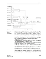
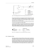
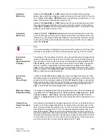
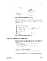
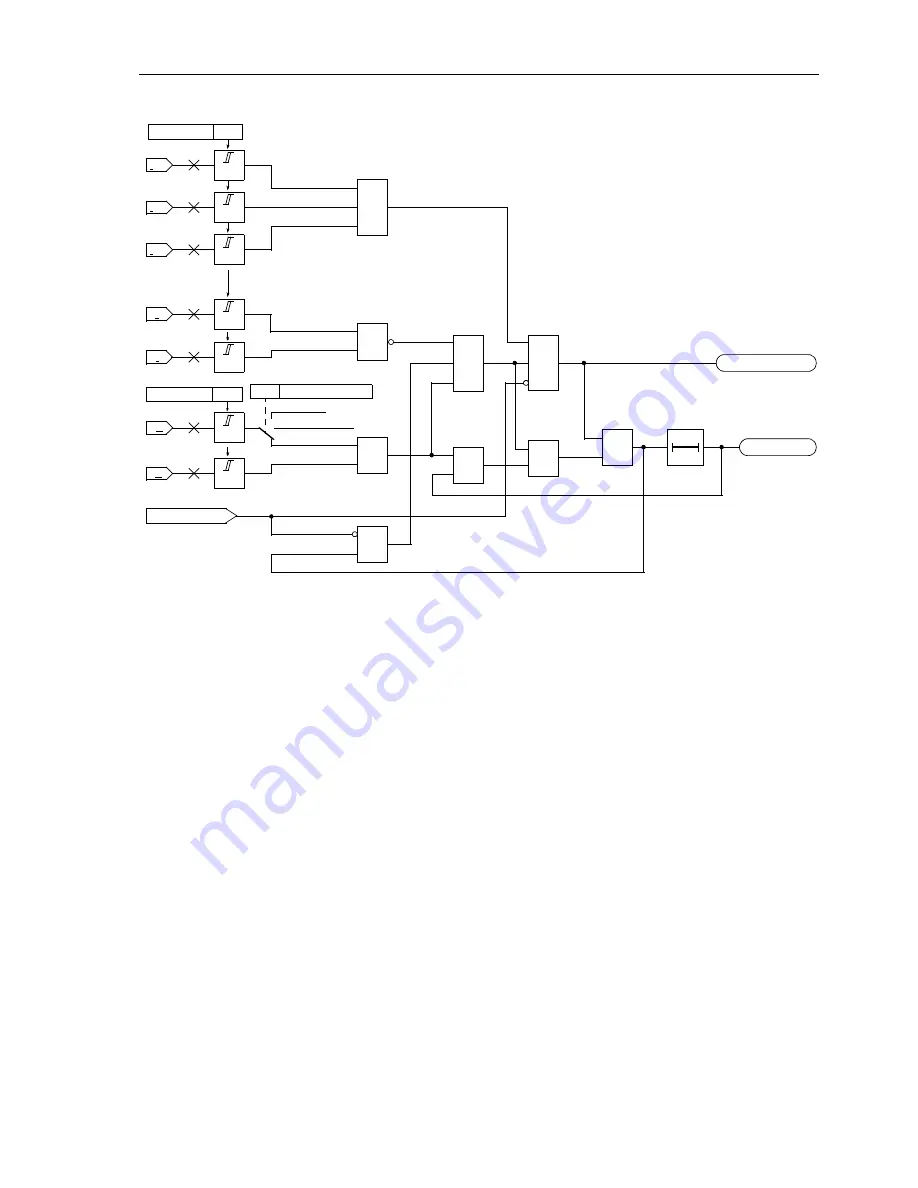
Figure 6-142 Logic diagram of the fuse failure monitor with zero and negative sequence system
Fuse Failure
Monitor
(Three-Phase)
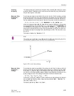
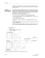
A three-phase failure of the secondary measured voltage can be distinguished from
an actual system fault by the fact that the currents have no significant change in the
event of a failure in the secondary measured voltage. For this reason, the sampled
current values are routed to a buffer, so that the difference between the present and
stored current values can be analysed to recognize the magnitude of the current dif-
ferential (current differential criterion). A three-pole voltage failure is detected if
•
all three phase–earth voltages are smaller than the threshold
FFM U<max (3ph)
,
•
the current differential in all three phases is smaller than the threshold
FFM Idelta (3p)
, and
•
all three phase current amplitudes are greater than the minimum current
Iph>
for
impedance measurement by the distance protection.
If no stored current values are present (yet), the current magnitude criterion is resorted
to. A three-pole system voltage failure is detected in this case if
•
all three phase–earth voltages are smaller than the threshold
FFM U<max (3ph)
,
•
all three phase current amplitudes are smaller than the minimum current
Iph>
for
impedance measurement by the distance protection, and
•
all three phase current amplitudes are greater than a fixed set noise threshold
(40 mA).
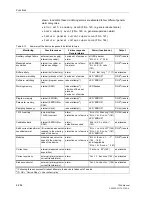
If such a voltage failure is recognized, the distance protection and all other functions
that operate on the basis of undervoltage (e.g. also weak infeed tripping, undervoltage
protection) are blocked until the voltage failure is removed; thereafter the blocking is
1pole dead time
3
I
0
3
I
2
3U
2
I
L1
I>
I>
U>
I>
U>
I
L2
I>
I
L3
I>
≥
1
2912
3U
0
≥
1
≥
1
&
≥
1
10 s
0
≥
1
VT FuseFail
Fuse–Failure
2911
≥
1
&
&
FNo 170
FNo 169
FFM U>(min)
FFM I< (max)
SystemStarpoint
Solid Earthed
0207
Peterson-Coil
Isolated
Содержание siprotec 7SA6
Страница 2: ...Siemens Aktiengesellschaft Book No C53000 G1176 C156 2 ...
Страница 18: ...xviii 7SA6 Manual C53000 G1176 C156 2 ...
Страница 32: ...Introduction 1 14 7SA6 Manual C53000 G1176 C156 2 ...
Страница 82: ...Hardware and Connections 2 50 7SA6 Manual C53000 G1176 C156 2 ...
Страница 119: ...SIPROTEC 4 Devices 4 25 7SA6 Manual C53000 G1176 C156 2 Figure 4 20 CFC Logic example ...
Страница 190: ...Configuration 5 62 7SA6 Manual C53000 G1176 C156 2 ...
Страница 559: ...Control During Operation 7 45 7SA6 Manual C53000 G1176 C156 2 Figure 7 45 Circuit breaker trip test in DIGSI 4 ...
Страница 652: ...Installation and Commissioning 8 78 7SA6 Manual C53000 G1176 C156 2 ...
Страница 724: ...Technical Data 10 56 7SA6 Manual C53000 G1176 C156 ...
Страница 800: ...Appendix A 76 7SA6 Manual C53000 G1176 C156 2 ...
Страница 866: ...Appendix B 66 7SA6 Manual C53000 G1176 C156 2 ...

