Functions
6-124
7SA6 Manual
C53000-G1176-C156-2
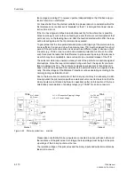
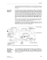
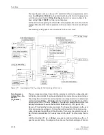
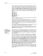
The logic diagram is shown in Figure 6-71. In addition to the curve parameters, a min-
imum time
3I0p MinT-DELAY
can be determined; below this time no tripping can oc-
cur. Below a current factor of
3I0p Startpoint
, which is set as a multiple of the
basic setting
3I0p PICKUP
, no tripping can take place.
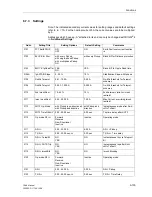
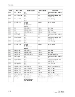
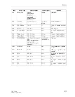
Further information regarding the effect of the various parameters can be found in the
setting information of the function parameters in Sub-section 6.7.2, refer also to Figure
6-75.
The remaining setting options are the same as for the other curves.
Figure 6-71
Logic diagram of the 3I
0P
–stage for the inverse logarithmic curve
Zero Sequence
Voltage Time Pro-
tection
(U
0
-Inverse)
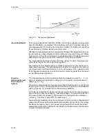
The zero sequence voltage time protection operates according to a voltage-depend-
ent trip time characteristic. It can be used instead of an inverse time overcurrent stage.
The voltage/time characteristic can be displaced in voltage direction for a determined
constant voltage (
U0inv. minimum
, valid for t
→ ∞
) and in time direction by a deter-
mined constant time (
T forw. (U0inv)
). The different characteristics and their un-
derlying formulae are shown in the Technical Data Section (10.5, Figure 10-5).
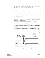
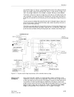
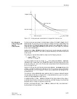
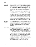
Figure 6-72 illustrates the functional principle. The tripping time depends on the level
of the zero sequence voltage U
0
. For meshed earthed systems the zero sequence
voltage increases towards the earth fault location. The inverse characteristic results in
the shortest command time for the relay closest to the fault. The other relays then re-
set.
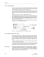
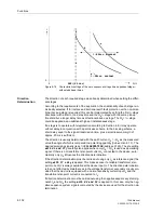
A further time stage
T rev. (U0inv)
provokes non-directional tripping with a volt-
age-independent delay. This stage can be set above the directional stage. When trip-
3140
Yes
No
Reverse
Forward
Non-Directional
„1“
≥
1
&
&
inrush-
stabilization
direction-
determination
forwards
reverse
&
&
Yes
No
3148
Yes
No
3I0p Telep/BI
permissive
teleprot..
switch on
to fault
≥
1
T
0
3173
SOTF Time DELAY
&
&
PICKUP
DIRECT.
3172
&
SOTF Op. Mode
I
E
3I
0P
3141
3154
t
3I
0
3145
T
0
3153
LOG Curve
3146
&
3142
T
0
3147
1309 >EF BLOCK 3I0p
3I0p InrushBlk
1357 EF 3I0p Pickup
3I0p SOTF-Trip
3149
EF 3I0p TRIP
1369
3I0p Startpoint
3150
≥
1
>EF Inst TRIP
3I0p PICKUP
Op. mode 3I0p
Add.T-DELAY
3I0p MinT-DELAY
Inactive
3I0p MaxT-DELAY
3I0p Time Dial
FNo 1310
Содержание siprotec 7SA6
Страница 2: ...Siemens Aktiengesellschaft Book No C53000 G1176 C156 2 ...
Страница 18: ...xviii 7SA6 Manual C53000 G1176 C156 2 ...
Страница 32: ...Introduction 1 14 7SA6 Manual C53000 G1176 C156 2 ...
Страница 82: ...Hardware and Connections 2 50 7SA6 Manual C53000 G1176 C156 2 ...
Страница 119: ...SIPROTEC 4 Devices 4 25 7SA6 Manual C53000 G1176 C156 2 Figure 4 20 CFC Logic example ...
Страница 190: ...Configuration 5 62 7SA6 Manual C53000 G1176 C156 2 ...
Страница 559: ...Control During Operation 7 45 7SA6 Manual C53000 G1176 C156 2 Figure 7 45 Circuit breaker trip test in DIGSI 4 ...
Страница 652: ...Installation and Commissioning 8 78 7SA6 Manual C53000 G1176 C156 2 ...
Страница 724: ...Technical Data 10 56 7SA6 Manual C53000 G1176 C156 ...
Страница 800: ...Appendix A 76 7SA6 Manual C53000 G1176 C156 2 ...
Страница 866: ...Appendix B 66 7SA6 Manual C53000 G1176 C156 2 ...

