Functions
6-133
7SA6 Manual
C53000-G1176-C156-2
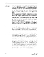
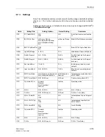
The position of the directional characteristic is determined with the setting parameters
Dir. ALPHA
and
Dir. BETA
(addresses
3162
und
3163
). As these set values are
not critical, the pre-settings may be left unchanged. This setting can only be modified
with DIGSI
®
4 under “Additional Settings”.
Finally, the threshold values of the polarizing signals must be set.
3U0>
(address
3164
) determines the minimum operating voltage for direction determination with U
E
.
If U
E
is not used for the direction determination, this setting is of no consequence. The
set threshold should not be exceeded by unsymmetries in the operational measured
voltage. U
E
is the sum of the phase voltages, i.o.w.
U
E
= U
L1
+ U
L2
+ U
L3
= 3·U
0
If the voltage dependent characteristic (U
0
inverse) is used as directional stage, it is
reasonable for the minimum polarizing voltage to use a value that is equal to or below
the minimum voltage of the voltage-controlled characteristic (address
3182
).
Only if the connection of the fourth current transformer
I4 transformer
(address
220
) =
IY starpoint
is registered in the
Power System Data 1 (P.System
Data 1)
(see 6.1.1), the address
3165
IY>
will appear. It is the lower threshold for
the current measured in the starpoint of a source transformer. A relatively sensitive
setting can be applied for this value, as the measurement of the starpoint current is
quite accurate by nature.
If the direction determination must be done with the negative sequence system sig-
nals, the setting values
3U2>
(address
3166
) and
3I2>
(address
3167
) are decisive
for the lower limit of the direction determination. The setting values must in this case
also be selected such that operational unsymmetry in the system does not lead to a
pick-up.
Teleprotection with
Earth Fault
Protection
The earth fault protection in the 7SA6 may be expanded to a directional comparison
protection using the integrated teleprotection logic. Additional information regarding
the available teleprotection schemes and their mode of operation may be obtained
from Section 6.8. If this is to be used, certain preconditions must already be observed
when setting the associated earth current stage.
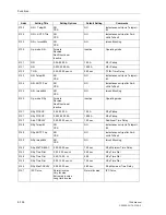
Initially it must be determined which stage must operate in conjunction with the tele-
protection. This stage must be set directional in the forward direction. If for example
the 3I
0
>–stage should operate as directional comparison, the address
3130
Op. mode 3I0>
is set to
Forward
(refer to “Definite Time Stages” above, page 128).
Furthermore, the device must be informed that the applicable stage has to function to-
gether with the teleprotection to allow undelayed release of the tripping during internal
faults. For the 3I
0
>–stage this means that address
3133
3I0p Telep/BI
is set to
Yes
. The time delay set for this stage
T 3I0>
(address
3132
) then functions as a
back-up stage, e.g. during failure of the signal transmission. For the remaining stages
the corresponding setting parameter is set to
No
, therefore, in this example: address
3123
3I0>> Telep/BI
for the 3I
0
>>–stage, address
3113
3I0>>> Telep/BI
for
the 3I
0
>>>–stage, address
3148
3I0p Telep/BI
for the 3I
0P
–stage (if this is used).
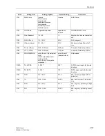
If the echo function is used in conjunction with the teleprotection scheme, or if the
weak-infeed tripping function should be used, the additional teleprotection stage
3IoMin Teleprot
(address
3105A
) must be set to avoid non-selective tripping dur-
ing through-fault earth current measurement. This setting can only be modified with
DIGSI
®
4 under “Additional Settings”. Further comments are given in Sub-section
6.8.2 under the margin heading “Earth Fault Protection Prerequisites”.
Содержание siprotec 7SA6
Страница 2: ...Siemens Aktiengesellschaft Book No C53000 G1176 C156 2 ...
Страница 18: ...xviii 7SA6 Manual C53000 G1176 C156 2 ...
Страница 32: ...Introduction 1 14 7SA6 Manual C53000 G1176 C156 2 ...
Страница 82: ...Hardware and Connections 2 50 7SA6 Manual C53000 G1176 C156 2 ...
Страница 119: ...SIPROTEC 4 Devices 4 25 7SA6 Manual C53000 G1176 C156 2 Figure 4 20 CFC Logic example ...
Страница 190: ...Configuration 5 62 7SA6 Manual C53000 G1176 C156 2 ...
Страница 559: ...Control During Operation 7 45 7SA6 Manual C53000 G1176 C156 2 Figure 7 45 Circuit breaker trip test in DIGSI 4 ...
Страница 652: ...Installation and Commissioning 8 78 7SA6 Manual C53000 G1176 C156 2 ...
Страница 724: ...Technical Data 10 56 7SA6 Manual C53000 G1176 C156 ...
Страница 800: ...Appendix A 76 7SA6 Manual C53000 G1176 C156 2 ...
Страница 866: ...Appendix B 66 7SA6 Manual C53000 G1176 C156 2 ...

