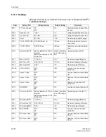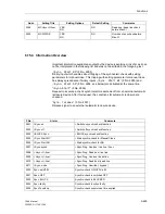
Functions
6-219
7SA6 Manual
C53000-G1176-C156-2
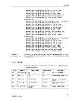
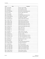
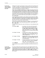
difference
Max. Freq. Diff
lie outside the permissible limit values. A precondition
for these messages is that voltages within the operating range of the relay are availa-
ble.
Operating modes
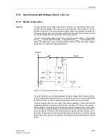
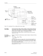
The closing check procedure can be selected from the following operating modes:
−
SYNC-CHECK
= Release at synchronism, that is, when the critical values
Max. Volt. Diff
,
Max. Freq. Diff
and
Max.
Angle Diff
lie within the set limits.
−
Usync> U-line<
= Release for energized bus-bar (U
bus
>) and de-ener-
gized line (U
line
<).
−
Usync< U-line>
= Release for de-energized bus-bar (U
bus
<) and ener-
gized line (U
line
>).
−
Usync< U-line<
= Release for de-energized bus-bar (U
bus
<) and de-ener-
gized line (U
line
<).
−
OVERRIDE
= Release without any check.
Each of these conditions can be switched to be effective or not effective; combinations
are also possible (e.g. release when
Usync> U-line<
or
Usync< U-line>
are sat-
isfied). Combination of
OVERRIDE
with other parameters is, of course, not meaningful.
The release conditions can be set individually for automatic and for manual closing,
e.g. you can permit manual closing at synchronism or dead line, whilst, before an
automatic reclosure, at one line end only dead line and, at the other, only synchronism
will be permitted.
Dead-line or
dead-bus closing
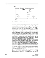
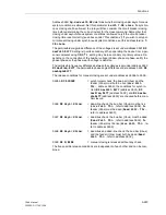
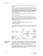
For release of the closing command to energize a voltage free line from a live bus-bar,
the following conditions are checked:
−
Does the feeder voltage U
line
lie below the set value
Dead Volt. Thr.
?
−
Does the bus-bar voltage U
bus
lie above the set value
Live Volt. Thr.
, but be-
low the maximum operating voltage
Umax
?
−
Does the bus-bar voltage frequency f
bus
lie within the permissible operating range
f
N
± 3 Hz?
When the conditions are satisfied, the closing command is released.
Corresponding conditions apply when switching a live line onto a dead bus-bar or a
dead line onto a dead bus-bar.
Closing at
synchronous
system conditions
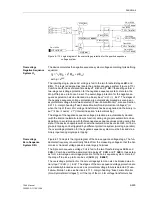
To release a closing command at synchronous system conditions, the following con-
ditions are checked:
−
Does the bus-bar voltage U
bus
lie above the set value
Live Volt. Thr.
, but be-
low the maximum operating voltage
Umax
?
−
Does the feeder voltage U
line
lie above the set value
Live Volt. Thr.
, but below
the maximum operating voltage
Umax
?
−
Does the voltage magnitude difference
|U
line
| – |U
bus
|
lie within the permissible
tolerance
Max. Volt. Diff
?
−
Do both the frequencies f
bus
and f
line
lie within the permissible operating range
f
N
± 3 Hz?
−
Does the frequency difference |f
line
– f
bus
| lie within the permissible tolerance
Max.
Freq. Diff
?
Содержание siprotec 7SA6
Страница 2: ...Siemens Aktiengesellschaft Book No C53000 G1176 C156 2 ...
Страница 18: ...xviii 7SA6 Manual C53000 G1176 C156 2 ...
Страница 32: ...Introduction 1 14 7SA6 Manual C53000 G1176 C156 2 ...
Страница 82: ...Hardware and Connections 2 50 7SA6 Manual C53000 G1176 C156 2 ...
Страница 119: ...SIPROTEC 4 Devices 4 25 7SA6 Manual C53000 G1176 C156 2 Figure 4 20 CFC Logic example ...
Страница 190: ...Configuration 5 62 7SA6 Manual C53000 G1176 C156 2 ...
Страница 559: ...Control During Operation 7 45 7SA6 Manual C53000 G1176 C156 2 Figure 7 45 Circuit breaker trip test in DIGSI 4 ...
Страница 652: ...Installation and Commissioning 8 78 7SA6 Manual C53000 G1176 C156 2 ...
Страница 724: ...Technical Data 10 56 7SA6 Manual C53000 G1176 C156 ...
Страница 800: ...Appendix A 76 7SA6 Manual C53000 G1176 C156 2 ...
Страница 866: ...Appendix B 66 7SA6 Manual C53000 G1176 C156 2 ...

